An Audio Frequency Induction Loop System, or AFILS, is a relatively new acronym for an old approach to assistive listening that is more commonly known as a "hearing loop". Using the full term may seem redundant to professionals in the hearing health industry because we know that the product of the inductive transmission is an audio signal, typically one that conveys speech information. Using the term AFILS or hearing loop is a matter of personal preference. But, it is imperative that AFILS/hearing loops are distinguished from neck loops. A neck loop is often supplied as a coupler to frequency-modulation (FM) systems and/or infra-red (IR) systems. At the outset, I will mention that all three of these assistive listening devices (ALDs) are capable of providing hearing instrument compatible auditory access through a telecoil! So, when you say something is "looped", you may want to clarify what you mean because facilities with hearing loops are not as common as you might think. This article will: review the rationale for ALDs; outline the advantages and disadvantages of hearing loops; list types of hearing loop installations; and present considerations for verifying the telecoil response in the hearing instrument.
Why Use Assistive Listening Technology?
- Provides greatest SNR benefit
- Promotes ease of listening
- Overcomes distance limitation
- Improves outcomes
- Complies with ADA requirements
There is no telling how many hearing instrument wearers are able to maintain a satisfactory level of speech reception at the at the expense of additional listening effort. Listening can be relatively effortless when you have a clear, consistent signal going directly to the hearing instrument. This benefit broadens the scope of assistive listening device candidacy from the handful who "really struggle" to the much larger pool who "manage to get by".
Regardless of how well or how easy it is to hear with the hearing instrument alone, the user must be in close proximity to the sound source because the benefit quickly diminishes with distance. With assistive listening, communication is possible over much greater distances. Therefore, the user is not limited to a conversational distance to maintain reception with a favorable SNR.
Disability is the reduced capacity to do something, and handicap means the inability to participate in those activities because of a disability. Assistive listening has been shown to reduce hearing-related disability and hearing handicap and increase satisfaction with amplification (Sheehan, 2007).
Businesses that serve the general public are required to comply with the Americans with Disabilities Act (ADA). The original version, published twenty years ago did not include a provision for hearing instrument compatibility. The mandate for hearing instrument compatibility will take effect March 15, 2012. Compatibility includes FM via neck loop, IR via neck loop and hearing loops (U.S. Department of Justice, ADA Standards for Accessible Design, 2010).
Get in the Hearing Loop Campaign
A joint project of the Hearing Loss Association of America (HLAA) and the American Academy of Audiology (AAA) called "Get in the Hearing Loop" was recently developed by the Executive Director of the Hearing Loss Association of America (HLAA), Brenda Battat, MA and then President of the American Academy of Audiology (AAA) Patricia Kricos, PhD. The goal is to educate laypeople and hearing professionals about hearing loops.
A significant contributor to the cause is a man named David Myers. He traveled overseas and experienced hearing aid compatible accessibility by simply flipping on his T-switch to access the direct audio signal in various public places. Dr. Myers was so impressed that he started a grassroots movement to Loop America (www.hearingloop.org). While he acknowledges the potential application of emerging wireless technologies, he defends loops as the only currently available choice for direct compatibility. According to his criteria, directly compatible means that no additional components are used and that the signal is universally accessible (personal communication, 2010).
Hearing Loop Advantages
The two main advantages of hearing loops over FM and IR systems are convenience and cosmetics. The convenience factor benefits the user and the venue. Privacy is another advantage of hearing loops and IR over FM systems.
- Convenience (user and venue)
- Cosmetics (user)
- Privacy (venue)
Allow me to share a typical hypothetical scenario. Theater patrons who want to use the publicly available assistive listening system will start by asking the ticket agent at the box office or an usher inside of the theater. This person or another staff member will request a form of identification and exchange it with an under-chin headset device. At this point, the patron explains that they wear hearing instruments that must be used with the assistive listening device. A puzzled look prompts a referral to the manager. The manager explains that their devices should be used instead of the personal hearing instruments. Clearly the manager is not aware that hearing instruments are specifically programmed for each individual. The manager explains that the facility is in compliance with the ADA and that they are sorry that the assistive listening device does not meet the "special needs" of the amplification wearer. The frustrated patron may be offered a refund but they are unable to access the auditory signal. This is not an extreme example.
With a hearing loop system, users simply activate their telecoils and receive the signal directly. An encounter with any venue staff is not necessary, unless the individual does not have a telecoil equipped hearing instrument or does not wear an instrument. In this case, the user will need to check out a device, similar to the logistics of using FM or IR.
From a venue management perspective, hearing loops are more convenient because there are no receivers to maintain for the telecoil users. This means fewer receivers in inventory and therefore less charging/changing of the batteries and sanitizing of earpieces.
From the perspective of a hearing professional, ordering a telecoil is much easier now than a decade ago, as today telecoils are offered in the majority of hearing instrument models (Table 1).
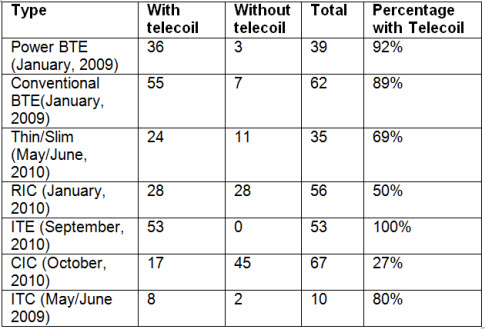
Table 1. Hearing aid models with and without telecoils, adapted from Hearing Review Products in 2009 and 2010 (see Reference List for a full listing of all Hearing Review Products issues used to compile this table).
When considering cosmetics, we remind ourselves that the telecoil is final link of the transmission chain. Because the telecoil is housed completely inside of the hearing aid, there are no additional components that must be worn to receive the signal. Users of hearing loops are generally indistinguishable from the rest of the audience.
Hearing loops can be designed to limit spillover. Infrared systems also have the ability to limit transmission for privacy concerns. With FM systems, a tech-savvy individual can scan and tune into the transmitting frequency to listen. This may be a concern for certain venues such as courtrooms or musical performances.
Telecoil User Advantages
Rather than list the following as advantages to hearing loops, it is more appropriate to treat these advantages separately because neck loops can be worn with FM and IR systems, as long as there is a headphone jack. Telecoils are:
- Inexpensive
- Feedback friendly
- Efficient transducers
Telecoil User Disadvantages
- Electromagnetic Interference (EMI)
- Larger hearing instruments
- Marginal Sound Quality
Because EMI is more prominent in the low frequencies, individuals with better hearing in this range would be expected to be more adversely affected. While there is tremendous flexibility in adjustment of parameters for microphone programs, the professional may not be able to adjust parameters to the same extent in the telecoil program.
Hearing instruments need to be somewhat larger to accommodate the telecoils. Cosmetic appearance remains an important factor in the selection process and the overall acceptance of the hearing instrument.
The audio product through a hearing loop is rather basic compared to proprietary wireless approaches used for personal listening. It is a mono signal with a limited frequency response. The hearing instrument may be able to apply algorithms to the telecoil signal (e.g. noise reduction). But, advanced features associated with better sound quality such as stereo listening and extended frequency response bandwidth are not possible with hearing loops at this time.
Hearing Loop Disadvantages
While there are many positive aspects to using a hearing loop, there are a few drawbacks for large venues. These include:
- High cost
- Difficult to analyze return on investment
- Limited availability
The invisibility listed as an advantage to hearing loop users can also be a detriment to the business owner who would like to track ALD usage. Owners who have opted for a more elaborate hearing loop system may be particularly inclined to show a return on their investment, especially when less expensive upgrades are available to achieve ADA compliance (i.e. neck loops). Advocates should be encouraged to obtain questionnaire data from patrons who wear hearing instruments and seek auditory access. Slight modifications to common audiological outcome measures can be made to make the measure venue specific (Sheehan, 2007).
Hearing loops are scarcely available in the United States. As we learned earlier in this article, there is growing momentum to change that. However, there is also reluctance to play "catch up" for fear that a better solution is just around the corner. Why did the U.S. not embrace widespread use of hearing loops earlier? The traditional purpose of the induction coil in the U.S. was to improve communication on the telephone, hence the term "tele-coil". To maximize the inductive flow for use on the phone, the coil is placed horizontally within the hearing instrument. Unfortunately, this orientation results in a poor response when the user uses their coil in a hearing loop. This could be the reason for low uptake of hearing loops in the United States.
Note: Sometimes 'portability' is cited as a disadvantage of hearing loops. This is not a valid point of comparison because all large area assistive listening approaches are permanently installed. Personal systems of various wireless transmission types are portable and may be used in short range applications.
Hearing Loop Fundamentals
The loop is simply a wire placed around an area, but not necessarily around a perimeter. The wire is usually laid flush with floors and walls and may even be placed in the baseboards or underneath the carpet. The audio output from the sound board is routed through the loop amplifier. The amplifier drives a magnetic current around the wire. Current is measured as the root mean squared (rms) value of milliamps per meter (mA/m).
Ideally, we would like to see the equivalent telecoil response match the microphone response (Putterman, 2010). But, the typical telecoil response has a 6dB per-octave rise before 1,000Hz before it flattens out. Some manufacturers have taken the approach of increasing the low-frequency response so that this program sounds richer, like the microphone response. Because electromagnetic interference tends to be in the low frequency range, it is particularly important to adjust that area first, starting with the lowest handle.
The frequency response of the hearing loop cannot be adjusted after it is installed. The point in which inductance equals the resistance is known as the corner frequency. This is directly related to the upper end of the frequency response of the hearing loop. The corner frequency should be above 5,000 Hz to avoid a loss of the high-frequency audio transmission (Dillon, 2001, p. 62). It will be interesting to see if novel loop amplifiers and installation techniques permit higher corner frequencies. Then the potential limitation of reduced bandwidth would be overcome.
Basic Installations
Many loops are very straightforward and can be installed by a layperson. These are usually counter loops and perimeter loops.
Counter loops (Figure 1), otherwise known as overspill loops, are used in one-to-one communication in a transient environment. Examples include reception areas and ticket counters equipped with microphones. In Figure 1, you can see that the outline of a person whose head is in the yellow area, an indication in this diagram that that signal is meeting the acceptable standard for signal strength (Figure 1 to Figure 6). Moving closer to the loop (to the right) would result in a signal that exceeds the standard for signal strength. Moving away from the loop (to the left) causes the signal to quickly dissipate. Note that the user is not surrounded by an actual wire. This is a common misunderstanding. The wire is contained in a small unit and projects in an outward path that the user is expected to enter.

Figure 1. Counter Loop (From Ampetronic, www.ampetronic.com/layouts_overview.asp)
Perimeter loops (Figure 2) are what most people think of when they hear of hearing loops. This is an example where the user physically surrounded by the wire. These can be utilized in small rooms (up to 80 feet circumference) as long as there is not a substantial amount of metal present. The goal is to have a uniform response in the entire perimeter. Spillover can reach outside of the perimeter up to 4 times the perimeter distance. Spillover is generally acceptable if there is not a need to contain the signal (e.g. living room, places of worship).
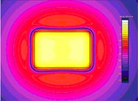
Figure 2. Perimeter Loop (From Ampetronic, www.ampetronic.com/layouts_overview.asp)
Advanced installations
Is professional installation necessary? A rule of thumb is to mirror the installation of the sound system. If it was professionally installed, then the hearing loop system should also be professionally installed. In these configurations, the user is not only surrounded by a wire perimeter, but the wire(s) may be crossing over within the listening area. Advanced installations include cancellation, array, low-loss and low-spill types.
The cancellation loop (Figure 3) is a single amplifier system with one continuous loop. However, the loop is arranged in an asymmetrical figure-eight so it appears as though there are two loops on the wiring diagram. The width of that smaller loop is adjusted tighter if there is a greater need to prevent spillover on that side.

Figure 3. Cancellation Loop (From Ampetronic, www.ampetronic.com/layouts_overview.asp)
Another single amplifier/ single loop configuration is the array loop (Figure 4). These are particularly useful if you are in a location where there is a lot of metal. A typical example is a church with fixed seating. Here, there are multiple figure-eight patterns configured with even spacing. The two red lines indicate the null points, which are used for transient environments such as the aisle where churchgoers would not be expected to stand for a long time.
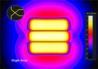
Figure 4. Array Loop (From Ampetronic, www.ampetronic.com/layouts_overview.asp)
Low-loss (Figure 5) and low-spill (Figure 6) arrays are advanced installations that utilize two amplifiers. These can accommodate more difficult seating areas, such as a balcony within a large theater. These are more complex because there is a gradient or slope to the floor. These installations use two different loops with two separate amplifiers. There are multiple figure-eight patterns and they are closely overlapped. The loop signals are 90 degrees out of phase with each other.
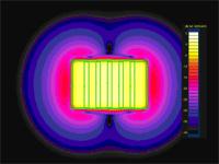
Figure 5. Low-Loss (From Ampetronic, www.ampetronic.com/layouts_overview.asp)
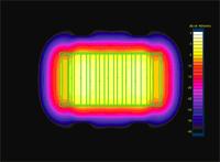
Figure 6. Low-Spill Loop (From Ampetronic, www.ampetronic.com/layouts_overview.asp)
IEC Standard
The International Electro technical Commission (IEC) standard 60118-4 is a commonly referenced standard for hearing loop installations. There are four required areas for measurement, which include: field strength; frequency response; background noise; and, the subjective test. All four metrics are made with a field strength meter (FSM). Measurements are made at multiple locations where listeners would be expected to be present during the event. One change in the new standard is that 'volume' is measured instead of 'area' to reflect the vertical dimension of installation. As such, measurements are made at 4 feet (1.2 meters) and 5.5 feet (1.7 meters) to simulate sitting and standing positions at each location.
Field strength is measured in milliamps per meter (mA/m). A hearing loop must be capable of producing a signal with peak value of 400 mA/m RMS using a 125 ms integration time (Ampetronic & Univox) to comply with the new standard. The previous standard used peak value of 100mA/m instead of an average value of 100 mA/m due to misinterpretations of the reference value. The 400 mA/m reference value now defines 0 dB for reference of subsequent measures. Field strength is measured at 1000 Hz first. Then 100Hz and 5000 Hz are measured and should be within +/- 3 dB of the 1000 Hz measure to ensure consistent frequency response in areas critical to speech. An alternative approach of using an artificial speech signal is also permitted (Univox).
Background noise is also measured by the FSM but unlike a sound level meter, this measure is an acoustic equivalent instead of a direct measure. The A-weighting is still used. Ideal background noise levels are below -47dBA, but measures below -32dBA are acceptable. Counter loops and other transient environments allow for more noise, but should be below -22dBA.
The subjective test or listening check is done by individuals with hearing loss via telecoil and individuals with normal hearing through the audio jack of the FSM. The sound quality assessment should note the presence humming, popping, fizzing or intermittent signals.
The Certificate of Conformity serves as a report card for each of the four measurement types. Markings are made on the blank gridlines to indicate where the measurements were obtained.
The AAA/HLAA Hearing Loop Task Force is developing criteria for watchdog consumers to ensure that venues continue to conform to the IEC standard. Simplified versions of the FSM are available for this purpose. Hearing Loop advocate/audiologist Juliette Sterkens, AuD, shared that in addition to the IEC measures, evaluators will look for signage that indicates that the venue is equipped with a hearing loop to obtain a passing score (personal communication, 2011).
Telecoil Verification
Telecoils are basically metal wires wrapped around a metal rod. A voltage is created or induced when an alternating magnetic field flows through the telecoil. The passage through the telecoil is called magnetic flux, and it is optimized when the rod part of the telecoil is perpendicular to the inductive signal. Factors that will affect the response are the size of the telecoil, the number of turns around the rod, whether or not it is a pre-amplifier and the orientation. If you are ordering a custom product and can specify the orientation, it is best to request a vertical orientation for patients who want to use a hearing loop.
Telecoil verification is important because hearing professional need: 1) a method to compare telecoil response within the hearing instrument depending on the intended application; 2) an alternative to a non-standardized listening check; and, 3) a method to compare to across hearing instruments.
Before we review common types of telecoil tests, it is important to keep in mind that the input signal directly affects the acoustic response (Table 2).
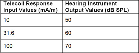
Table 2. Equivalent values for telecoil inputs (ma/M) and acoustic outputs (dB SPL)
Test box systems have magnetic field simulator tool that is used to evaluate the response. It is usually located inside the test box (Figure 7) but there is also at least one device that measures this outside of the test box (Figure 8). Internal magnetic simulators permit telephone and hearing loop simulations. External magnetic simulators permit telephone simulation and are especially useful in finding the "sweet spot" or position of maximal response.
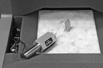
Figure 7. Frye Fonix 8000 sound chamber telecoil board with vertical positioning (Frye Electronics, 2011, p. 75).
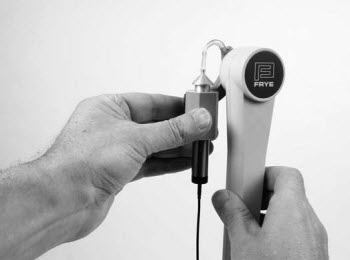
Figure 8. Frye Fonix telewand for testing telecoil (Frye Electronics, 2011, p. 76).
If your test box has a magnetic simulator, you can run two different measurements to verify telecoil performance: SPLITS and SPLIV. The SPL part of the acronym is the familiar 'Sound Pressure Level'. The 'IS' stands for Inductive Simulation. The difference is 'T' for Telephone and 'V' for Vertical. As mentioned earlier, horizontal orientation is optimal for reception with the telephone (Figure 9) and vertical orientation is optimal for reception in a hearing loop (Figure 10). These measures reflect an average value of 1000 Hz, 1600 Hz and 2500 Hz.
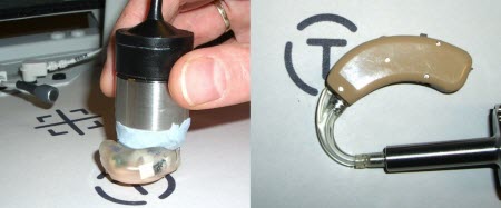
Figure 9. Magnetic simulator test (SPLITS) in the Verifit test box. The faceplates are parallel to the floor of the test box chamber. (Audioscan User Guide v.3.6, p.45; Retrieved from: www.audioscan.com/resources/usersguides/Verifit Users Guide_3_6.pdf).

Figure 10. Magnetic simulator test (SPLIV) in the Verifit test box. The faceplates are perpendicular to the floor of the test box chamber. (Audioscan User Guide v3.6, p.46, Retrieved from: www.audioscan.com/resources/usersguides/Verifit Users Guide_3_6.pdf).
Once we have determined that our test box has a magnetic simulator and we know how to position the instruments horizontally and vertically, we will get SPLITS and SPLIV results on the display. We can also see other values for Telephone Sensitivity (TS) and Test Loop Sensitivity (TLS). These values have deducted the reference test gain/position value.
Note: One of the changes in the American National Standards Institute (ANSI) standards from 1996 to 2003 is clarification that these tests are "relative", "simulated" and "equivalent" values. So, depending on your test box system and which standard you are using, the letters "R", "S" and/or "E" may precede the TS and TLS test values. The purpose of this terminology changes is to remind the professional that these are acoustic values to electromagnetic measures.
Figure 11 shows a sample test run on the Verifit test box system. The solid green line is the response curve for the telephone simulator, which corresponds to the average SPLITS value of 87 dB SPL and the RSETS value of -16.0. This means that the telecoil signal for phone usage is 16 dB lower than the microphone response (not shown) of the hearing instrument. Likewise, the dashed magenta line is the response curve for the test loop, which average SPLIV value in the box at 95dB and the RTLS value of -8 dB. This means that the telecoil signal for hearing loop usage is 8 dB lower than the microphone response (not shown) of the hearing instrument.
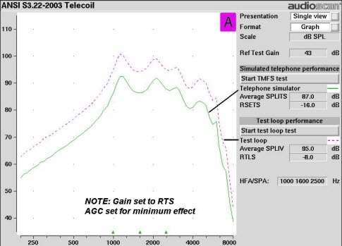
Figure 11. Verifit simulated telephone and loop performance tests (Audioscan User Guide v3.6, p.47, Retrieved from: www.audioscan.com/resources/usersguides/Verifit Users Guide_3_6.pdf)
This screen shot (Figure 11) leads us to believe that the telecoil is aligned more closely to the vertical axis than to the horizontal axis because there is a better response in the loop test than the telephone test. The more practical message is that the professional needs to increase the "gain" in the telecoil program for both applications. The telephone user needs to have a greater increase than the loop user to match the microphone response. It would be beneficial to view the microphone response curve on the same screen for comparison because a single number does not tell us much about the response across frequencies.
Notice on the screen shot that we were using the ANSI 2003 standard for measurement. Because this test protocol sets the magnetic simulator in your test box to 31.6 mA/m, it is not appropriate to use when evaluating telecoil performance intended for hearing loops. So, dispensing professionals should conduct their own test protocol in their test box, utilizing a 100 mA/m to compare to the IEC standard for hearing loop installations.
Summary
This article provided an overview of hearing loop technology, including various configurations for usage and their relative merits. This information is valuable to audiologists in making clinical decisions regarding hearing aid selection, programming, and verification. Through the efforts of individual audiologists as well as the "Get in the Hearing Loop" campaign by AAA and HLAA, there is increased awareness of hearing loops among the general public and increased usage of hearing loops in some areas of the U.S. As the professional working directly with the hearing impaired individuals who can benefit from this trend, audiologists should understand hearing loops and how they fit into the overall arsenal of assistive technology available today.
References
Ampetronic. New Requirements for Audio Induction Loops in 2007. www.ampetronic.com/docs/standards_compliance.pdf
Audioscan. (2010). Verifit user's guide version 3.6. Dorchester, Ontario: Etymotic Design Incorporated. Retrieved from: www.audioscan.com/resources/usersguides/Verifit Users Guide_3_6.pdf
Dillon, H. (2001). Hearing aids. New York: Thieme.
Frye Electronics. (2011). FONIX 8000 hearing aid test system operator's manual, version 2.12, Tigard, OR: Frye Electronics, Inc.
Hearing Review Products. (2010, October). Technology guide: CIC (Completely-In Canal) Retrieved from: www.hearingreview.com/archives.asp
Hearing Review Products. (2010, September). Technology guide: Full & half shell ITE (Inside-The-Ear) hearing aids. Retrieved from: www.hearingreview.com/archives.asp
Hearing Review Products. (2010, May/June). Technology guide: Power BTE (Behind-The-Ear) hearing aids. Retrieved from: www.hearingreview.com/archives.asp
Hearing Review Products. (2010, January). Technology guide: RIC/RITE hearing aids. Retrieved from: www.hearingreview.com/archives.asp
Hearing Review Products. (2010, February). Technology guide: Thin-/slim-tube hearing aids.
Retrieved from: www.hearingreview.com/archives.asp
Hearing Review Products. (2009, May/June). Technology guide: ITCs (Inside-The-Canal) hearing aids. Retrieved from: www.hearingreview.com/archives.asp
Hearing Review Products. (2009, January). Technology guide matrix: Conventional BTE hearing aids. Retrieved from: www.hearingreview.com/archives.asp
Putterman, D.B. (2010). Difference between default telecoil and programmed microphone frequency response in behind-the-ear hearing aids. (Independent Studies and Capstones,Paper 599, Program in Audiology and Communication Sciences, Washington University School of Medicine, 2010). Retrieved from: digitalcommons.wustl.edu/pacs_capstones/599
Sheehan, J. (2007). Multidimensional outcomes measures of FM system usage in places of worship. (Doctoral dissertation,University of Florida, 2007). Retrieved from: etd.fcla.edu/UF/UFE0018580/sheehan_j.pdf
Univox. (2006). Standard for measurement of induction loops - IEC 60118-4:2006. Retrieved from:univox.eu/Products/Hearing-loop-systems/Measurement-Control/Standard-for-measurement-of-induction-loops-IEC-60118-4-2006
U.S. Department of Justice, American with Disabilities Act. (2010). 2010 ADA Standards for Accessible Design. Retrieved from: www.ada.gov/2010ADAstandards_index.htm