Editor's note: This article is a text format of a recorded webinar.
Hello, everyone. My name is Wendy Crumley-Welsh. I am the product manager for the ICS product line for Otometrics, and this is Evoked Potentials Part 2. Today we will be covering Electrocochleography (ECochG), middle-latency responses or MLR, P300, and cortical responses. Part 1 of this course covered good practices with auditory brainstem response (ABR) testing. Even if you are not using ABR testing routinely in your clinic, I would recommend perusing that course for good tips on electrode placement and optimal testing conditions, as well as interpretation of results.
What are evoked potentials (EP)? EPs are electrical signals generated by the nervous system in response to a stimulus. They are event-related, which means they are evoked by the onset of the stimulus. They are very useful in diagnosing a variety of neurological disorders.
Evoked potentials occur within a specific time frame. Electrocochleography occurs between 1-3 msec; ABR between 0-20 msec; middle-latency evoked potentials occur between 10 and 50 msec; late potentials occur between 50 and 1,000 msec which include the P300 and cortical responses.
An EP is a far-field recording because electrodes are placed on the scalp far from the neural generator. The electrodes are assigned as active (+) or reference (-) and ground. We always record from a pair of electrodes, typically Cz to A1 or Cz to A2 for middle-latency responses (MLR), P300 and cortical responses. Using a horizontal montage and recording between A1 and A2 for ECochG will be discussed as well.
We record from the non-inverting electrode (+) and an inverting electrode (-). One thing to take into consideration is the physical condition of the electrodes and the measured impedance values. You are picking up the response from these electrodes, so if you have poor placement or if the electrodes are faulty or dirty, you will reduce your chances of recording quality EP data.
Common-mode rejection is used by all EP systems. To produce a waveform, the voltages at each of the electrodes are subtracted from each other by the amplifier. Electrical activity or noise that is common to both electrodes is canceled out and only the response voltage remains. This is called common mode rejection. The response voltage is then amplified. Low and equal impedance at the electrode sites is essential for common mode rejection to work well. Again, it is also important that the electrodes are cared for properly since this is the medium used to collect very small evoked potential responses.
Patient Preparation
Typically we use the 10-20 system for electrode placement. I want to point out that true Cz gives a much larger amplitude response than high forehead placement. That is important when you are collecting middle or late latencies, which can be very small.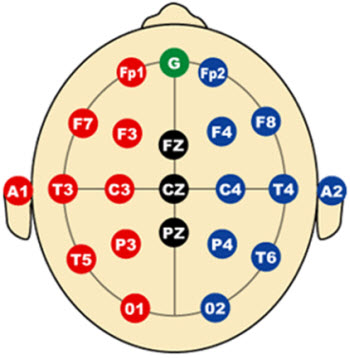
Figure 1. International 10-20 electrode placement map.
Figure 1 represents the common locations for electrode placement. You can see Cz at the top of the head. The left side is always odd numbers. The right side is always even numbers, so A1 is the left ear, and A2 is the right ear. Sometimes you will see M1 or M2 used which corresponds to the left and right mastoids. Fpz is high forehead. We will use C3 to A1 and C4 to A2 for MLR.
So once you have your electrodes connected to the patient, you want to make sure to check the impedance. On the Chartr EP system, all you have to do is click the impedance button in the software. The Charter EP 200 comes with a remote control so you can easily push the "impedance" button on the remote and see your impedance numbers on the preamp. It is especially useful if you are doing pediatrics, but also useful for adults so that you do not have to go back to the computer to see your impedance readings. You can remain near your patient to rescrub if needed.
The impedance readings are constantly updating, so if you press down on the electrode or take one off and rescrub and put it back on, you can look at the preamp and can see that the impedances are updated. There is no need to push a button again once you start the impedance check. On the computer screen, if you have no electrode plugged in (or a faulty electrode) it will display "open," but the preamp impedance display will say "99.9." Impedance values of up to 80kOhms will be displayed. Low electrode-impedance readings (less than 5kOhms) and balanced (no more than 2 kOhms difference between each pair of electrodes) will ensure that common-mode rejection works most effectively.
Once you have entered the patient information into the software, connected the electrodes and checked the impedance, select your protocol. The Chartr EP200 system has default protocols installed for ABR, ASSR, ECochG, MLR and late responses. There are two add-ons that are available for purchase: the VEMP with the EMG monitor and the P300. The VEMP is currently pending FDA approval for use in the United States.
It is always a good idea to do a listening check before you use your equipment, whether it is your audiometer or your EP system. You want to use subjects with hearing thresholds within normal limits, and ask them to listen to the stimulus. It should be barely audible between 0 and 5 dB. A good suggestion is to establish a routine such as checking the ABR stimulus every Monday of the week.
If the softest level a normal hearing listener can hear the stimulus is 20 dB, then there is a 20 dB correction factor. So if the protocol intensity level is 60 dB, you are actually only delivering 40 dB. It is also recommended that you perform the listening check for all the transducers used in your clinic: inserts, headphones and bone oscillator. If you have to make a correction factor, it is recommended that you call your local representative or manufacturer and have the system re-calibrated.
Electrocochleography
What is the purpose of an ECochG? Typically, we use it to see if the patient is having an issue with the inner ear system, such as endolymphatic hydrops or vestibular hydrops. Endolymphatic hydrops is a result of increased pressure and fluid mismatch between the endolymph and perilymph in the inner ear. Because both fluids contain differing chemical components, a mixture of the two fluids can interfere with the proper transmission of signal to neural receptors, causing the brain to receive disorderly signals. This condition also causes swelling within the inner ear. This is why patients complain of severe vertigo and aural fullness. Endolymphatic hydrops is sometimes used synonymously with Meniere's disease, although there are characteristics than can differentiate the two. ECochG can pick up on the increased endolymphatic pressure.
There are two different types of electrodes to use for ECochG. The first one is the gold-foil Tiptrode (Figure 2). The Tiptrode serves as an electrode AND delivers the stimulus via the silicone tubing which is connected to the insert earphone.
Figure 2. Gold-foil Tiptrode insert for use with ECochG.
The ear canal must be prepped before using Tiptrodes. You can use a little bit of NuPrep on a Q-tip and scrub the inside of the ear canal. Keep in mind that the skin in the ear canal is very thin and sensitive, so while the canal should be cleaned, be aware of how deep you are scrubbing. In addition, be sure to perform an otoscopic exam before placing the Tiptrode. Finally, make sure that there is no cerumen in the ear canal.
One thing to consider about ECochG and cerumen removal is the method of removal. ECochG is often one part of a general vestibular battery, so if you perform cerumen removal using water irrigation and still have air calorics to perform as part of a VNG exam, it may alter the results if moisture still remains in the ear. The moisture will change the temperature of the air when irrigating and can cause erroneous results. So, if the patient has cerumen and you know you are going to do a VNG with an air irrigator afterwards, make sure the doctor knows to use manual cerumen removal.
After scrubbing the ear canal, some people like to put a conductive paste or cream on the gold foil. While it is not always necessary, you can achieve good impedance if you do that. You do have to be careful though, because the cream or paste can remove the gold foil from the ear tip.
When attaching the ear tip onto the tubing of the Tiptrode cable, there is an alligator clip on the end. You want to make sure that alligator clip touches the gold foil that extends down the black tubing. If it does not touch that gold foil, you will not get good results. Sometimes those alligator ends have a tendency to splay out a little bit. You can just bend them back into position to insure they are making contact with the gold foil.
Try to be careful when compressing the foam tip. We typically roll it between our fingers to compress it, but you have to take extra care to not remove the gold foil from the foam tip. Make sure that you place the ear tip completely inside the ear canal, where the black tubing connected to the eartip is flush with the entrance of the ear canal. You do not want to have the tip out into the concha, because the stimulus level you are delivering will not be exact if the ear tip is positioned improperly. Because Tiptrodes have their own silicone tubing and this tubing directly affects the stimulus, they should be coupled directly to the insert earphone transducer box, not to the insert earphone tubing.
Attach the lead into the preamp making sure that the lead and the tubing are not intertwined together. In the Chartr EP 200 system, Channel 1 reference is always the ear that is being stimulated. You can set up a two-channel protocol, making sure the ear you are stimulating is your reference and that the active is in the opposite ear.
The one-channel ECochG with a Tiptrode shown below is a horizontal montage (Figure 3). Ground is on the middle forehead, Channel 1 reference is the ear being stimulated, and Channel 1 active is the ear not being stimulated. You will get a much better ECochG if you are recording using a horizontal montage. When you switch test ear, you must manually switch the electrodes in the preamp because it is a one-channel recording. Channel 1 active for the right ear moves to Channel 1 reference, and the reference moves to the active, so the reference is always the ear that you are stimulating. This will ensure the AP is correctly amplified.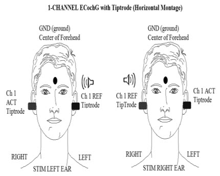
Figure 3. Horizontal montage for recording ECochG.
The tympanic membrane (TM) ECochGtrode (Figure 4) is different from the Tiptrode because it is inserted deeper into the ear canal and will actually touch the ear drum during the test. Because it is placed closer to the source of the potential you are collecting, it is the best electrode to use.
The electrode has a tacky silicone blue end. The electrode plugs into a sheilded cable that splits into two ends. The green end of this cable is ground. The red end of the cable is the reference electrode (test ear). To correctly connect the shielded cable to the preamplifier remember that Channel 1 reference is the test ear and corresponds to the red end of the sheilded cable. The non-test ear electrode connects to Channel 1 Active. The forehead electrode connects to ground.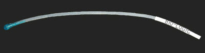
Figure 4. Extra tympanic ECochG electrode, manufactured by BioLogic.
Prior to placement of this electrode, you must perform an otoscopic examination. If there is cerumen, it should be removed before attempting insertion of the electrode. If you identify a perforated eardrum, do not use an ECochGtrode. Carefully guide this electrode down the ear canal until it butts up against the eardrum, and then you are going to place the insert earphone alongside it to hold it in place and to deliver the stimulus. The benefit of this electrode is that you are closer to the neural generator, so it gives you a more robust response.
Since you are unable to 'scrub' the eardrum, the impedance is usually quite high with the TM ECochGtrode. Because it is located so close to the cochlea, the effect on the AP is usually minimal. In other words, you can obtain a repeatable ECochG despite the very high impedance. If necessary, you can place two CCs of saline into the ear canal and then drain out the ear, which helps reduce the impedance. Again, you do not want to do this if you plan on doing air irrigations during the same visit. Make sure the saline is body temperature, so it does not cause nystagmus or a vestibular effect.
Impedances are basically dependent on two things: conductivity gel and placement. Before inserting the electrode, place a small amount of conductive gel on the blue end that touches the eardrum. Be sure not to use too much gel because it can sometimes block the insert earphone and reduce the stimulus output. In addition, the gel will ensure that the blue tip does not adhere to the eardrum.
If the electrode is sitting in the ear canal or is up against the canal wall, you are not going to get good impedances. It is not uncommon, however, for the impedance to be greater than 20 kOhms, but you be able to get something 30 or below. If your electrode impedance is really high, there is a good chance that it is not placed properly.
As discussed earlier in this presentation, inter-electrode impedance should be very similar. This is the one exception to that rule. If you are using a TM ECochGtrode, the impedance will always be significantly higher than the surface electrodes; that is not uncommon.
Because of the deep insertion required for the ECochGtrode, you need to prepare the person for what is going to happen. I would say, "I am going to put this electrode down in your ear canal. It is going to touch your eardrum. It should not hurt, but you may hear a thud or you may feel some pressure. It is not uncommon for your throat to feel a little bit itchy when it is placed up against your eardrum. Your voice may sound funny or hollow." Begin carefully to guide it down slowly, until you start to feel some resistance. Sometimes that resistance is the bend in the ear canal, so the other tip is to pull up and back on the pinna to straighten out that ear canal.
With experience, you will get a feel for when you have made contact with the eardrum. One, you will feel a little bit of pushback on the electrode, but the other thing is you will see the person wince a little bit. Do not be alarmed; that is not uncommon. If they have a tendency to move away from the electrode or jerk a little bit sideways, you are going to need to make sure that you give them a second to rest, and then you are probably going to need to push it back down a little further, because chances are when they moved, the electrode has moved away from the eardrum. I recommend that if you are performing this test with an ECochGtrode on patients that you perform it on yourself also to get a feel for the sensation and the depth of the electrode. This helps immensely when counseling the patient.
Once the ECochGtrode is placed and touching the eardrum, hold on to the electrode as you insert the insert earphone so that electrode does not nudge further against the eardrum. You can hold the electrode, but I find that taping it in place also works well. You can tape it to the earlobe or the cheek, depending on how the lead sits in the ear canal.
The montage for the ECochGtrode is a horizontal montage (Figure 3) and the same as with a Tiptrode. Ground is the center of the forehead. The Channel 1 reference is the ear being tested, and the Channel 1 active is the opposite ear. If you are using this montage, the active potential (AP) will be going upwards in the positive direction. Remember that before you switch test ears, you must physically switch the electrodes in the preamp.
Clinical Uses of ECochG
Why do we use the ECochG test? Sometimes it assists with Ménière's diagnosis or endolymphatic hydrops, but you cannot diagnose Ménière's disease with ECochG alone. A full case history and a series of tests are usually required before the physician determines the diagnosis. A person with Ménière's disease will typically have vertigo, fluctuating hearing loss, a low, roaring tinnitus, and aural fullness. This makes sense, because if you have swelling of the semicircular canals, typical symptoms will be vertigo and some aural fullness. If there is swelling of the cochlea, then hearing loss will be a common symptom because the cochlea is not going to be functioning properly.
Some people prefer the TM ECochGtrode to the Tiptrode to enhance Wave I and increase the amplitude. One thing to note, however, is if the patient has severe or high-frequency hearing loss, you may not be able to record a sufficient ECochG. The AP of the ECochG is the same as Wave I of the ABR, so if there is cochlear damage in the presence of hearing loss, it will be more difficult to record the ECochG.
We may also use ECochG for identification of the cochlear microphonic. You may be looking at this in a patient who has auditory neuropathy spectrum disorder. In that case, we use the parameters of the ECochG, but we will record rarefaction and condensation runs to pick up the cochlear microphonic. If you want to learn more about cochlear microphonic, you can refer to Part 1 of the Evoked Potential series.
ECochG Test Parameters
The ECochG requires a loud stimulus of at least 90 dB. It can be detected as low as 60 dB, but amplitude increases with an increase of intensity. We are not looking for threshold with ECochG. We are looking for a difference between the summating potential (SP) and AP, so if we can obtain a response with a larger amplitude, we will be able to easily discern the difference between SP and AP. Most everyone uses an insert earphone transducer. I presume you could use headphones if you were using the ECochGtrode.
Use an alternating polarity for general ECochG testing, but again, not for auditory neuropathy where we would need to see the cochlear microphonic with rarefaction and condensation runs. Use a click stimulus with 100k gain. The high- and low-pass filters are set at 10 to 1500 Hz, respectively, with the artifact filter on.
Because the response occurs between 1 to 3 milliseconds, our window size can be smaller than for ABR. A 5 to 10 millisecond sweep time is appropriate, with at least 2,000 sweeps. Sometimes you need that many sweeps; sometimes you do not. You can always stop it beforehand if a robust response is recorded. The ECochG uses a much slower rate than the ABR at 7.1. There is an acquisition delay of -1, which is a pre-stimulus delay so you will see a little bit of the waveform before the stimulus onset. The stimulus onset is marked by a line on the waveform. From this point you can mark your baseline and see the response.
There a couple of differences between parameters for the Tiptrode and the TM ECochGtrode. The stimulus is the same, but the gain will be different. For the TM ECochGtrode, instead of using a 100k gain, often 50k gain is used. Why is that? Because, the closer the electrode is to the neural generator, the response is larger and not as much amplification is needed. The TMtrode is on the eardrum, which is closer to the neural generator than with the Tiptrode, so we use lower gain. The filters remain the same, but the artifact reject can be turned off for the TMtrode. The sweep time, pre-stimulus delay, and the rate are the same for both electrode types.
Why do we use such a slow rate? The response amplitude decreases with a faster rate, and we want to see a nice, large response, with a distinct difference between the SP and AP. Using a slower rate gives a more robust response. The alternating polarity will cancel out the cochlear microphonic so we can easily see the components of the response: Wave I/AP and the SP.
Components of the ECochG
The cochlear microphonic (CM) is the first component of the ECochG waveform. This is a stimulus-dependent cochlear response, which changes direction with changing polarity. Rarefaction and condensation stimuli will actually elicit response that are mirror images of each other, so if you use an alternating click, you will not see the CM.
The SP is a direct-current distortion potential arising from the Organ of Corti hair cells. The SP is often seen as a leading hump on the AP or Wave I, although sometimes it can appear as a completely separate hump (Figure 5). The last thing we look for is the AP, which the same as Wave I of the ABR, and is an alternating-current response generated by the cochlear end of the VIIIth nerve. The AP represents the summed response of thousands of firing auditory nerve fibers.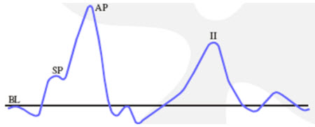
Figure 5. Textbook ECochG response, where BL= baseline; SP= summating potential; AP= action potential.
For ECochG responses collected with Tiptrodes, an SP/AP ratio of less than 50 percent is within normal limits. For ECochG responses collected with TMtrodes, an SP/AP ratio less than 35% is within the normal range. Figure 6 depicts a normal ECochG response in contrast with an abnormal response. The software will calculate the SP/AP ratio for you when you mark baseline, SP, and AP.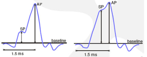
Figure 6. A normal (left panel) and abnormal (right panel) response where the SP is elevated in relation to the baseline.
Middle-Latency Responses
The middle-latency response is often referred to as MLR or AMLR. AMLR stands for auditory middle-latency response. The MLR is derived from the medial geniculate body, inferior colliculus and the primary auditory cortex. The most important thing to keep in mind as we move into middle and late responses is that the patient cannot be asleep for this testing. As you move further up into the brain, the patient needs to stay awake and alert in order to maintain a response. The MLR is used to assess auditory cortical function, whether the person has function or does not have function. If there is an abnormality, you can determine which side is affected.
The MLR produces waveforms that are identifiable at or near threshold and may be useful in identifying low-frequency auditory sensitivity. However, the ABR latencies are more consistent between tests than with MLRs. MLR has larger amplitude than the ABR and is less dependent on neural synchrony. The latency of the response is unchanged whether the patient is asleep or awake, but the amplitude is highly affected. The amplitude is smaller if the patient is asleep, so arrange for the patient to be awake during testing. You definitely do not want the patient to be anesthetized or have light sedatives because this will eliminate the MLR response.
What montage is used for MLR? A horizontal montage of Cz/A1/A2 and mid-forehead is ground. As stated previously, true Cz on the top of the head gives you the best response.
A change in intensity does not affect latency, so unlike the ABR, when you go down in intensity, there is not a significant shift in latency. Po, Pa and Pb are the labels used to mark the MLR at high intensities. As you decrease intensity, only Pa will remain. With reduced intensity, you will see a slight increase in latency and a decrease in amplitude for Pa. The response is not highly frequency-dependent, but an increased stimulus frequency will result in slight reduction of latency and lower amplitudes. The stimulus rate is slow, between 6 and 10 stimuli per second. The MLR response occurs between 10 to 80 milliseconds. The Na will occur at 12 to 18 milliseconds, Pa at 25 to 30 milliseconds and Pb at approximately 50 milliseconds.
The default protocol in the Chartr EP 200 system uses a high intensity stimulus at 80 dBnHL with a rarefaction click at a rate of 7.7 per second and 75k gain. The response amplitude decreases with faster rates, so it is easier to record the MLR if a slower rate is used. The filters are 10 to 300 Hz, so notice they are much narrower than for ECochG or ABR. Remember, the ECochG was 10 to 1500 Hz and the ABR is 100 to 3000 or 100 to 1500 Hz. Artifact reject should be on.
The sweep time (epoch or time window) must be set so you capture the response you are measuring. It is only 10 milliseconds for an adult ABR because the response usually occurs between 0 and 6 msec. The MLR is a much later potential so the sweep time is relatively long: 80 milliseconds. It is a large response so not as many sweeps are needed to collect this response: about 1,000 sweeps will do, and you can always stop the collection if a robust response appears. A 10 millisecond pre-stimulus delay is recommended. A recorded response is shown in Figure 7. The left panel is a left ipsilateral response at 80 dB, and the right panel is the contralateral response. Po, Na, and Pa are labeled.
Figure 7. MLR response as recorded on the Chartr EP 200 system by Otometrics. Click Here to View a Larger Version of Figure 7 (PDF)
P300
P300 is considered a late-latency response that generally occurs at approximately 300 milliseconds. P300 is dependent on internal thought process and is generated by the hippocampus where short-term memory functions are stored. The patient must be awake and alert to the stimuli. Again, use the same montage, Cz to A1 or A2 and mid-forehead as ground. What is unique about P300 is two different stimuli: frequent and infrequent are presented. Typically 1000Hz is the frequent stimulus and 2000 Hz is the infrequent stimulus. The patient is instructed to count the number of times they hear the higher-frequency tone, or the infrequent stimulus.
The ratio is 5 frequent to 1 infrequent stimulus with approximately 20 infrequent stimuli presented randomly during the recording. The patient cannot predict the pattern of when the infrequent stimulus occurs, so they attend better to the task.
The P300 is generated from conscious discrimination of different stimuli. The more difficult the discrimination task, the smaller the P300 would be. In other words, the closer the stimuli are in frequency the smaller the response. For example, the discrimination task between 1000 to 1100 Hz will result in a less robust response than if 1000Hz and 2000Hz are used. You can present the stimuli binaurally as well as monaurally.
A funny consequence of the test is at the end of a collection the patient often wants to know if the number of stimuli they counted was the correct number that were presented. Of course, it does not matter if the patient counted all of the 2000-Hz tones correctly. The purpose of the counting task is to ensure they are attending to the stimuli and that their brain is staying alert. That attention is what generates the P300 response.
The P300 is a slow, broad response with a peak at 250 to 300 milliseconds. A decrease in amplitude and an increase in latency are indicative of dementia, Alzheimer's or other various neurological or psychiatric diseases. Therefore, if there is a disorder of cognitive functioning, the P300 typically will be abnormal.
The parameters for the P300 vary from the other evoked potentials. You will have the option to set the intensity for both the frequent and infrequent stimuli; they do not have to be the same. The default intensity for both stimuli is 75 dBnHL. Insert earphones with an alternating polarity for the tone bursts is the default. The frequency can be selected for both tones, but the default is 1000Hz and 2000Hz. The ramp and plateau cycles are much broader than with an ABR tonebursts.
The gain is usually lower for later potentials because they are such large responses. For example, only a gain of 30k is needed for the P300. Filter settings are usually narrower for later potentials. Filter settings of 1 to 30 Hz are recommended for the P300 response. The artifact filter is on. Sweep time must be longer, around 500 milliseconds because the response occurs around 300 milliseconds. There will be a -50 pre-stimulus delay and a default of 500 sweeps because the response is so large. The stimulus rate is 1.1 per second.
Unlike other auditory tests, sometimes you will get artifact responses in your P300 due to eye blinks. Some people recommend using one channel to record the P300 and the other channel to monitor the eye blinks. Place the electrode either above and below one eye or to the outer corners of each eye, like ENG placement, to record the eye blinks.
If you are experiencing this, you may hook up that channel, ask them to blink their eye, and then they look at the amplitude of the response of those eye blinks. Set the artifact reject level for the P300 just below that amplitude. That can help ensure that the eye-blink artifacts are rejected and not included in the P300 response.
Cortical Responses
The cortical response is derived from a slow-vertex response. It produces waveforms that are identifiable near a threshold and may be useful in identifying hearing status using toneburst stimuli. It is used for medical legal cases or for patients who are difficult to test with behavioral audiometry. The one disadvantage to corticals is that the response is not fully mature until the late teen years. The montage is Cz to A1/A2 with mid-forehead ground. Again, use the true Cz for better responses.
What does the patient do during the test? They can read a book. What you do not want them to do is quickly scan the text, because that eye movement will cause artifacts in your response, but they can be sitting there relaxed and looking through a book. For more information on cortical responses, Dr. Guy Lightfoot's Web site, corticalera.com, is very informative.
A cortical response protocol is not included in the EP 200 software. You can easily add a new protocol. Begin by selecting an ALR protocol and go Setup→New Protocol. You can modify the existing parameters and save as a new protocol. The transducer can be inserts or headphones with a starting stimulus level of 70 dBnHL. If you are using the cortical potentials to estimate hearing, you will want to create multiple protocols using different tone burst frequencies. As a suggestion, you can choose 500, 1000, 2000 and 4000 Hz. Select a linear envelope.
You are will have to determine how many cycles for ramp and plateau to use which will vary depending on the stimulus frequency. (Please see the article "The N1-P2 Cortical Auditory Evoked Potential for Threshold Estimation" by Guy Lightfoot, PhD on our AOL web channel for ramping specifics. The direct link to this article is: www.audiologyonline.com/articles/article_detail.asp?wc=1&article_id=2342.) These should be very broad tonebursts, and so it is almost like a pure tone being delivered. The gain is 30k because it is such a large response. The high-pass and low-pass cutoffs are 1 to 1500 Hz, respectively. Artifact reject is on. A 500 millisecond sweep time, 0 pre-stimulus delay, 30 sweeps and a slow rate of 0.7 per second is recommended.
The cortical response consists of an N1 and P2, and sometimes P1 can be labeled as well. A decreased intensity will result in amplitude decrease, but the latency does not change significantly. Why use only 30 sweeps? This is because the response habituates, so very few sweeps are needed. You may get a beautiful response after 10 sweeps, and if you keep on collecting out to 30, 40, 50 or more sweeps, the response may disappear or become very, very small. Therefore, if the response is robust after only a few sweeps, stop the collection.
The response occurs between 50 and 300 milliseconds. N1 occurs at approximately 100 milliseconds and P2 at approximately 200 milliseconds. Clinically, you may want to complete three runs, sum them together and then mark N1 and P2.
Figure 8 shows data collected on a young audiologist. The response was collected using a
2000 Hz tone burst presented at 70, 50 and 30 dB with N1 to P2 marked. These are nice, repeatable responses. The benefit is that a robust response appears with very few sweeps. The cortical response is an excellent tool that hopefully it will catch on in the U.S.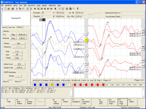
Figure 8. Cortical response for 2000 Hz tone burst presented at 70, 50 and 30 dB with N1 to P2 marked for left ear (blue) and right ear (red). Click Here to View a Larger Version of Figure 8 (PDF)
Conclusion
You can find more information on EP, VNG and all our products on our website: www.otometrics.com. As always, check our Web channel on AudiologyOnline, because we routinely add new courses: www.audiologyonline.com/channels/otometrics.asp.
Electrocochleography, MLR, P300 and Cortical Responses, Evoked Auditory Potentials Part 2
August 8, 2011
Share:

Related Courses
1
https://www.audiologyonline.com/audiology-ceus/course/improving-ehdi-with-caeps-clinical-31492
Improving EHDI with CAEPs: Clinical Assessment of the Cortical Auditory Evoked Potential in Children with Hearing Loss
This course will provide an overview of cortical auditory evoked potentials, current research, benefits and limitations to using CAEPs in a busy clinic, and several case studies.
auditory, textual, visual
Improving EHDI with CAEPs: Clinical Assessment of the Cortical Auditory Evoked Potential in Children with Hearing Loss
Presented by Elizabeth Musgrave, AuD, CCC-A
Course: #31492Level: Intermediate1 Hour
AAA/0.1 Intermediate; ACAud/1.0; BAA/1.0; CAA/1.0; Calif SLPAB/1.0; IACET/0.1; IHS/1.0; Kansas, LTS-S0035/1.0; NZAS/1.0; SAC/1.0
This course will provide an overview of cortical auditory evoked potentials, current research, benefits and limitations to using CAEPs in a busy clinic, and several case studies.
2
https://www.audiologyonline.com/audiology-ceus/course/what-s-new-in-otometrics-32529
What's New in the Otometrics Bio-logic Line of Devices?
This presentation will highlight new innovations in technology within the new generation Bio-logic devices. These technologies are meant to help to improve efficiency and also add to the armamentarium of tests that can be performed with one device. Technology that will be discussed will be for ABR, ASSR and DPOAEs. ABR topics will cover data collection from both ears at the same time and spread spectrum technology. ASSR will highlight mixed rate ASSR and DPOAE will showcase the use of an FM signal, binaural OAE, pressurized OAEs and threshold estimation software to estimate audiometric thresholds using DPOAEs.
auditory, textual, visual
What's New in the Otometrics Bio-logic Line of Devices?
Presented by Diane Sabo
Course: #32529Level: Advanced1 Hour
AAA/0.1 Advanced; ACAud/1.0; BAA/1.0; CAA/1.0; IACET/0.1; IHS/1.0; Kansas, LTS-S0035/1.0; NZAS/1.0; SAC/1.0
This presentation will highlight new innovations in technology within the new generation Bio-logic devices. These technologies are meant to help to improve efficiency and also add to the armamentarium of tests that can be performed with one device. Technology that will be discussed will be for ABR, ASSR and DPOAEs. ABR topics will cover data collection from both ears at the same time and spread spectrum technology. ASSR will highlight mixed rate ASSR and DPOAE will showcase the use of an FM signal, binaural OAE, pressurized OAEs and threshold estimation software to estimate audiometric thresholds using DPOAEs.
3
https://www.audiologyonline.com/audiology-ceus/course/guide-to-bithermal-caloric-testing-815
A Guide to Bithermal Caloric Testing
The purpose of this course is to provide an in-depth discussion of the caloric testing portion of the VNG/ENG test battery. Content will include descriptions of testing procedures, analysis and interpretation of results.
auditory, textual, visual
A Guide to Bithermal Caloric Testing
Presented by Amanda Cerka Mroz, AuD, FAAA, CCC-A
Course: #815Level: Intermediate1 Hour
No CEUs/Hours Offered
The purpose of this course is to provide an in-depth discussion of the caloric testing portion of the VNG/ENG test battery. Content will include descriptions of testing procedures, analysis and interpretation of results.
4
https://www.audiologyonline.com/audiology-ceus/course/auditory-brainstem-responses-abr-to-27716
Auditory Brainstem Responses (ABR) to Brief-tone Bone-conducted Stimuli
This webinar will discuss the history of brief-tone bone-conduction auditory brainstem (ABR) research and its clinical applications today as an essential component of early diagnosis of hearing loss in infants. Methodology and interpretation of bone-conduction ABRs to estimate bone-conduction hearing thresholds will be discussed in detail and cases will be provided to illustrate the principles explained. This webinar will be open captioned.Please note: You may earn ABA Tier 1 credits for this course if you complete it as part of the course 27885, "Auditory Evoked Responses for Infant Hearing Assessment Series". Course 27885 contains recordings of all three events from our 2016 series on Auditory Evoked Responses for Infant Hearing Assessment. ABA Tier 1 CEUs can be earned only when all modules are completed as part of course 27885.
auditory, textual, visual
Auditory Brainstem Responses (ABR) to Brief-tone Bone-conducted Stimuli
Presented by Susan Small, PhD
Course: #27716Level: Intermediate1 Hour
AAA/0.1 Intermediate; ACAud/1.0; BAA/1.0; CAA/1.0; Calif SLPAB/1.0; IACET/0.1; IHS/1.0; Kansas, LTS-S0035/1.0; NZAS/1.0; SAC/1.0
This webinar will discuss the history of brief-tone bone-conduction auditory brainstem (ABR) research and its clinical applications today as an essential component of early diagnosis of hearing loss in infants. Methodology and interpretation of bone-conduction ABRs to estimate bone-conduction hearing thresholds will be discussed in detail and cases will be provided to illustrate the principles explained. This webinar will be open captioned.
Please note: You may earn ABA Tier 1 credits for this course if you complete it as part of the course 27885, "Auditory Evoked Responses for Infant Hearing Assessment Series". Course 27885 contains recordings of all three events from our 2016 series on Auditory Evoked Responses for Infant Hearing Assessment. ABA Tier 1 CEUs can be earned only when all modules are completed as part of course 27885.
Please note: You may earn ABA Tier 1 credits for this course if you complete it as part of the course 27885, "Auditory Evoked Responses for Infant Hearing Assessment Series". Course 27885 contains recordings of all three events from our 2016 series on Auditory Evoked Responses for Infant Hearing Assessment. ABA Tier 1 CEUs can be earned only when all modules are completed as part of course 27885.
5
https://www.audiologyonline.com/audiology-ceus/course/intraoperative-neurophysiologic-monitoring-introduction-to-29252
Intraoperative Neurophysiologic Monitoring: An Introduction to the Operating Room for the Audiologist
This is the first webinar in a 3-part series on Intraoperative Neurophysiologic Monitoring, that will be taking place on AudiologyOnline in June 2017. This course will provide an overview of the operating room (OR) workplace to the generally unfamiliar audiologist. OR personnel and commonly enountered protocols will be discussed, along with an overview of neurophysiologic testing conducted in the OR.Please note: You may earn ABA Tier 1 credits for this course if you complete it as part of the course 29665, "Interoperative Neurophysiologic Monitoring: Basics and Beyond." Course 29665 contains recordings of all three events from our series on Interoperative Monitoring. ABA Tier 1 CEUs can be earned only when all modules are completed as part of course 29665.
auditory, textual, visual
Intraoperative Neurophysiologic Monitoring: An Introduction to the Operating Room for the Audiologist
Presented by Krysta Gasser Rutledge, AuD
Course: #29252Level: Introductory1 Hour
AAA/0.1 Introductory; ACAud/1.0; BAA/1.0; CAA/1.0; Calif SLPAB/1.0; IACET/0.1; IHS/1.0; Kansas, LTS-S0035/1.0; NZAS/1.0; SAC/1.0
This is the first webinar in a 3-part series on Intraoperative Neurophysiologic Monitoring, that will be taking place on AudiologyOnline in June 2017. This course will provide an overview of the operating room (OR) workplace to the generally unfamiliar audiologist. OR personnel and commonly enountered protocols will be discussed, along with an overview of neurophysiologic testing conducted in the OR.
Please note: You may earn ABA Tier 1 credits for this course if you complete it as part of the course 29665, "Interoperative Neurophysiologic Monitoring: Basics and Beyond." Course 29665 contains recordings of all three events from our series on Interoperative Monitoring. ABA Tier 1 CEUs can be earned only when all modules are completed as part of course 29665.
Please note: You may earn ABA Tier 1 credits for this course if you complete it as part of the course 29665, "Interoperative Neurophysiologic Monitoring: Basics and Beyond." Course 29665 contains recordings of all three events from our series on Interoperative Monitoring. ABA Tier 1 CEUs can be earned only when all modules are completed as part of course 29665.