
The pinna carries out the important function of shaping the acoustic properties of sound entering the ear. The frequency shaping provided by the pinna enhances the frequencies important for speech understanding and provides cues that allow the brain to decode and analyze signal location in the environment. When hearing is impaired, the natural boost in sounds provided by the pinna is often insufficient to ensure audibility of these essential cues. The obvious solution to this problem is to amplify those frequency regions important for speech perception to restore audibility. Hearing instruments, in general, do a good job of this, but often disrupt the cues provided by the pinna depending on the location of the sound inlet (Franks, Feth, & Daniloff, 1981; Gartrell & Church, 1990). As a result, the altered pinna cues can add to a perception that hearing instruments provide unnatural sound.
A design technique that places the microphone in the external ear near the concha cymba makes use of the natural effects of the pinna, as they relate to directivity, high frequency amplification and wind noise reduction. The microphone is housed in a plastic capsule attached to the body of the hearing instrument via thin wires encased in a flexible translucent plastic tube seated in the wearer's concha. The remaining components of the hearing instrument, including the battery, microprocessor and the receiver are encased in a custom shell that sits in the ear canal. The custom shell may be a Completely-in-the-Canal (CIC) or other style. This design also allows for venting around the in-the-ear component to provide open comfort similar to that of an open BTE. This article will review the underlying principles that guided the design process of Remote Microphone (RM) hearing instrumentation at ReSound.
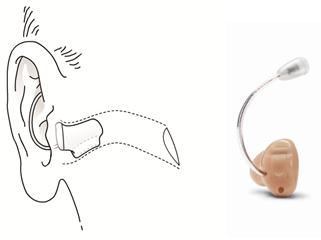
Figure 1. In the RM design, the placement of the microphone in the concha cymba hides the microphone not only for improved cosmetics but also for improved acoustic performance due to pinna effects and protection from turbulent wind noise.
Acoustic Performance and Microphone Location
Prior to reaching the ear, a sound wave interacts with the environment. Absorptions, reflections, and resonances inherent in any acoustic environment provide amplification or attenuation to various frequency regions. Before a sound wave is coded in the cochlea, the structures of the outer and middle ear alter its frequency response, and these changes depend on the direction of arrival as well as the frequency of the incoming sound. The combined effect adds information to the sound for the listener, providing important cues for spatial hearing.
The frequency shaping characteristics of the human pinna are an important consideration in the design of a hearing instrument. It has been shown that when the microphone is placed in the outer ear or ear canal, as is the case with custom hearing aids, reflections and diffractions due to the geometry of the pinna result in greater sound pressure at the port of the microphone, especially for high frequencies. By contrast, the input sound to a microphone on a traditional BTE instrument sitting just above the pinna, receives no frequency shaping from outer ear geometry and only subtle treatment from head and body reflections and diffractions of sound (Bentler & Pavlovic, 1989). This difference in sound energy as a function of microphone placement is referred to as the microphone location effect. The microphone location effect is taken into account in the electroacoustic design of hearing instruments. Thus, the amplifier in a BTE must provide more gain than an in-the-ear device to achieve the same response in the real ear. While this ensures that prescribed real ear gain targets can be reasonably met regardless of hearing instrument style, it does not ensure that appropriate acoustic cues are provided to the user. This is because cues due to spectral shaping of sounds coming from varying directions may be lost.
Localization, Directivity and Hearing in Noise
Transfer functions from the free field to the eardrum demonstrate that sounds from 180° behind the listener are less intense than sounds from 0° in front of the listener for frequencies above 1 kHz (Shaw, 1974). Since the outer ear naturally provides enhanced directivity, a RM instrument may provide good natural directivity to aid in localization and hearing in noise. In fact, it has been reported through clinical experience that some users of Completely-in-Canal (CIC) instruments hear well in background noise as the deep placement of the microphone in the ear canal provides directivity and thus helps with hearing in background noise. Figure 2 shows a comparison of the directivity indices of the open ear, a CIC and a RM instrument. This figure illustrates how the directivity of the outer ear has been maintained when the hearing instrument microphone is placed within the pinna.

Figure 2. A comparison of the directivity indices of the open ear (Red), a traditional CIC instrument (Blue) and a RM (Black) instrument.
Van den Bogaert and colleagues investigated the significance of microphone placement on the preservation of spatial awareness and localization ability (Van den Bogaert, Carette, & Wouters, 2011). These investigations focused on left-right, up-down and front-back localization by hearing impaired listeners fit with different styles of devices. Subjects were asked to identify where a sound was coming from by pointing in the appropriate direction. The task was repeated using a RM device, a BTE, a CIC, and a BTE that utilizes ear-to-ear communication to restore the front-biased directionality that naturally occurs due to the pinna effect through two-microphone directional processing. Additionally, objective measures of the spectral cues provided by each type of device were also obtained on a manikin.
It was theorized that localization errors would increase as spectral cues were interrupted due to microphone placement and signal processing. No significant differences were found for left/right and up/down localization ability between unaided conditions or for the different styles of hearing instruments. However, marked differences were demonstrated in front-back localization, with the percentage of front/back confusions being reduced in conditions when the RM instrument was used. Consistent with this finding, the objective measurements for the RM placement showed that the spectral information provided was similar to what was measured on the manikin with an open ear. These results support that the RM position is effective at preserving the pinna effect.
Preserved localization ability might seem of modest benefit to hearing instrument wearers. However, localization allows listeners to form 3-dimensional auditory representations of their surroundings, offering further benefits in terms of hearing in noise. The impact of preserved spectral cues due to microphone placement was demonstrated in an investigation of the performance of RM instruments at the Walter Reed Army Medical Center (Cord, Block, & Papke, 2011). Researchers compared three hearing aid styles across a group of 12 inexperienced hearing aid users with bilateral mild sloping to severe sensorineural hearing loss. Participants trialed three different styles of hearing instruments with the same signal processing over a time course that included a one-week acclimatization period and one-week of wear time. These included a traditional CIC, RM device and an Open Fit BTE. The order in which the devices were used was counterbalanced to ensure that order effects did not influence the results. The devices were compared across several categories including: cosmetic appeal, sound quality, overall performance and others. Given the theoretical concepts of the impact of microphone placement on pinna effects and hearing in noise, comparison of performance in background noise across the devices was also investigated.
The comparison of the performance in background noise across instruments was obtained using the Hearing in Noise Test (HINT) (Nilsson, Soli & Sullivan, 1994). The HINT procedure employs an adaptive method to determine the SNR at which stimulus sentences are correctly identified 50% of the time. In this study, noise was presented at a fixed 65 dBA level from speakers located at 90°, 180° and 270° azimuth and the sentence levels were varied depending on the accuracy of the listener's response from 0° azimuth. Figure 3 displays the results of these tests.
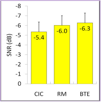
Figure 3. Comparison of HINT results for CIC, RM and Open BTE form factors.
The results suggest that the RM device can provide similar performance in background noise relative to a dual microphone open fit BTE. This is important when considering which form factor is best for patients. Some may prefer an instrument that fits completely within the ear canal such as a CIC or RM device. The RM device can provide directional performance that is comparable to an open fit BTE with dual mics. While the results for the CIC were still not statistically different than the open fit BTE, the risk for occlusion is much greater in the CIC given the restricted venting available. Taken together, the RM device can provide similar performance in background noise as an open fit BTE, but can also provide a more cosmetically appealing option for your patients as well as natural protection from wind noise. Additionally, when compared to a traditional CIC, the venting options available for a RM device provide more flexibility to combat occlusion-related complaints.
Wind Noise Reduction
Wind noise is generated from turbulent airflow over any surface. Given that this turbulence is essentially an air pressure fluctuation, hearing aid microphones are susceptible to receiving these wind fluctuations and amplifying them as they would any other sound pressure fluctuation (Kates, 2008). Several solutions to reduce wind noise in hearing instruments, such as the use of wind screens and digital algorithms, have been researched and implemented over the years. The RM design utilizes the physical and acoustic properties of the outer ear to improve performance in wind noise.
In situ measurements (Dillon, Roe & Katch, 1999) indicate that the greatest amount of wind noise turbulence typically occurs in the areas behind the pinna. This area of greatest wind turbulence is often the exact location of the microphone ports on BTE hearing instruments. By contrast, very little turbulence is measured in the superior portions of the concha. The placement of the microphone behind the cartilage of the helix and concha inherent in the RM design provides a physical barrier protecting the inlet of the microphone from turbulent air flow. When the microphone is placed within the concha cymba, the effect of wind noise is greatly reduced. While wind noise reduction algorithms may be effective at reducing wind noise, it is good practice to optimize the acoustic signal entering the system first rather than relying on an algorithm to alter the signal at a later stage.
Maximum Stable Gain
Undoubtedly, one of the most important lessons learned in the development of mini-BTE devices was to think out of the box, or rather out of the hearing aid case, when deciding where hearing aid components should be placed relative to the design. The design concepts implemented for very small cosmetically appealing Receiver-In-the-Ear (RITE) hearing instruments were made possible once the receiver was relocated in the patient's ear canal. While the initial act of moving the receiver initially provided benefits related to the size of the device, other benefits regarding the amount of available gain before feedback were also achieved. Specifically for RITE technology, the placement of the receiver in the ear canal reduced the transmission of structurally-born vibrational energy that can lead to feedback. In a conventional BTE, gain can sometimes be limited by feedback oscillation that is caused by mechanical or acoustic vibration within the casing itself. This phenomenon is typically masked in an open configuration because the feedback path is determined mainly by acoustic leakage from the ear canal rather than internal pathways in the device (Hallenbeck & Groth, 2008). However, added gain is demonstrable when the receiver from the BTE is relocated to an occluding earmold (Ross & Cirmo, 1980)
The "out of the case" design process utilized in RM hearing instruments builds upon these same concepts. Given that the microphone is placed outside of the hearing aid case in the upper portion of the concha of the outer ear, the same benefits related to gain before feedback that is possible with closed RITE devices can be achieved using a RM design. When custom devices are constructed with the receiver and microphone in the same housing, mechanical feedback pathways exist for the structural transmission of sound energy. By removing the microphone from the instrument case, the mechanical feedback pathway is reduced due to the increase in distance between components and decrease in points of contact between microphone, shell and receiver. Similar to RITE devices, the benefits in terms of microphone externalization in RM open configurations will be masked by the direct feedback pathway of sound leaving the ear canal. However, the closed RM configuration reduces the primary acoustic feedback pathway by occluding the ear canal and decreases the transmission of structurally transmitted feedback via external microphone placement. This manifests itself most notably in the closed configurations with no or minimal venting. Because of the reduced probability of feedback, a tightly sealed custom shell RM device can provide power comparable to an ITE device in the size of a CIC.
This concept was investigated during the development of RM CIC products. Twenty-six ears were fit with custom RM CIC products and traditional CIC products. The devices were closely matched in terms of the shape, size and the fit of the shell. A measurement of maximum stable gain (MSG) was obtained by setting the gain handles of the fitting software to a flat level and gradually increasing the gain until the point of feedback. Both the traditional CICs and RM CICs were tested using this technique. A baseline insertion gain measure was obtained to ensure that differences in device calibration did not influence the data. These findings are shown in Figure 4 and suggest that, on average, one might expect a 9 dB increase in maximum gain before feedback in RM CICs as compared to traditional CICs.
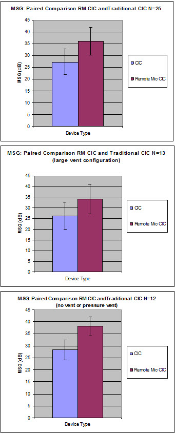
Figure 4: Comparison of the amount of gain before feedback (maximum stable gain, or MSG) between traditional CICs and RM CICs measured in real ears. Top graph includes all devices tested; secondary graphs are grouped based upon power level and venting.
While the increase in gain before feedback is related to the microphone relocation, it was considered that other factors such as the fit of the device and the venting of the device are probably also factors. The data previously presented contains information for various power levels and vent configurations. When these groups are separated into two smaller groups the difference is slightly larger for high power closed configurations and slightly less for lower power devices with larger vents. While some difference between RM CICs and traditional CICs might be expected in devices with large vents, the amount of the difference actually observed was somewhat unexpected and not readily explained.
In order to reduce variability due to fit, which was suspected to influence the differences between RM CIC and traditional CICs measured on real ears, a second experiment was completed using a device made for a KEMAR with 2 microphones. One of the microphones was located in a position typical for standard CIC instruments. The other microphone was placed in a position consistent with the design of the RM CIC. These 2 microphones could be switched on and off using development software without disturbing the placement of the instrument in the KEMAR ear. Four devices were manufactured, each with a different vent size. Figure 5 is a photo of one of these devices in the KEMAR ear.
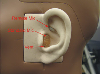
Figure 5: Device designed to test amount of gain before feedback in RM CIC design and traditional CIC design, while controlling for the effects of fit and venting.
Results from this laboratory test consistently demonstrated that the RM position provided more gain before feedback in comparison to the traditional microphone location (Figure 6). It is also interesting to note that as vent size increased, the amount of available gain before feedback decreased.
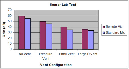
Figure 6: Results comparing the amount of gain before feedback as it relates to microphone location.
Summary
RM hearing instruments provide benefit for a wide range of hearing-impaired patients. These benefits include decreased wind noise and directivity based upon the microphone placement in the concha cymba. Research participants were found to make fewer localization errors when fit with RM devices than with the typical microphone placement in BTE devices, most likely due to preservation of spectral cues. Speech-recognition-in-noise test results also supported the positive effect of preserving the spectral shaping of the pinna. Research participants who trialed conventional CIC, open fit BTE with directionality, and RM instruments demonstrated similar benefit with each device type. Design characteristics, due to component placement, provide greater flexibility relative to other custom devices when choosing between options such as vent size and power level. Clinical results indicated significantly greater gain before feedback with the RM concept than with conventional custom devices for a variety of venting sizes. When fit of the device was controlled in a lab experiment, it was shown that up to 5 dB added stable gain can be expected with RM instruments compared to conventional custom devices.
References
Bentler, R.A. & Pavlovic, C.V. (1989). Transfer functions and correction factors used in hearing aid evaluation and research. Ear and Hearing, 10, 58-63.
Cord, M., Block, K. & Papke, T. (2011, March). Efficacy of the remote microphone hearing aid for novice hearing aid users. Paper presented at the Joint Defense Veterans Audiology Conference, San Diego, CA.
Dillon, H., Roe, I., & Katch, R. (1999, January 13). Wind noise in hearing aids: Mechanisms and measurements. National Acoustics Labs Australia: Report to Danavox, Phonak, Oticon and Widex.
Franks, J.R., Feth, L.L., & Daniloff, R.G. (1981). Hearing aid microphone location effects on speech discrimination in noise. Ear and Hearing, 2(6), 241-50.
Gartrell, E.L., & Church, G.T. (1990). Effect of microphone location in ITE versus BTE hearing aids. Journal of the American Academy of Audiology,1(3), 151-3.
Hallenbeck, S.A. & Groth, J. (2008). Thin-tube and receiver-in-canal devices, positive feedback on both! Hearing Journal, 61(1), 28-34
Kates, J. (2008). Digital hearing aids (Chapter 6). San Diego, CA: Plural Publishing.
Nilsson, M., Soli, S.D., & Sullivan, J.A. (1994). Development of the Hearing in Noise Test for the measurement of speech reception thresholds in quiet and in noise. Journal of the Acoustical Society of America, 95(2), 1085-1099.
Ross, M., & Cirmo, R. (1980, January) Reducing feedback in a post-auricular hearing aid by implanting the receiver in an earmold. Volta Review, 40-44.
Shaw, E.A.G. (1974). Transformation of source pressure level from the free field to the eardrum in the horizontal plane. Journal of the Acoustical Society of America, 56, 1848-61.
Van den Bogaert, T., Carette, E., & Wouters, J. (2011). Sound source localization using hearing aids with microphones placed behind-the-ear, in-the-canal, and in the pinna. International Journal of Audiology, 50, 164-76.