
Introduction:
The advent and clinical implementation of probe microphone real-ear measurements has introduced hearing health care professionals to a range of new terminology and procedures. Often, confusion arises as clinicians attempt to sort through the real-ear literature. Unfortunately, this confusion precludes some clinicians from conducting real-ear measurements which could improve hearing instrument fittings.
To address this concern, this article will offer an overview of real-ear measurement procedures. Specifically, we will provide the reader with various real-ear measurement terms, explanations of how they are conducted, and most importantly, a rationale as to why you might want to perform them. Readers interested in learning more about probe microphone real-ear measurements are referred to Mueller, Hawkins and Northern (1992).
Getting started: Pre-measurement factors:
While probe microphone real-ear measurements represent a valid, repeatable and reliable method of assessing the real-ear performance of hearing instruments, there are a number of factors that can impact test results (Hawkins and Mueller, 1986, 1992; Ickes et al., 1991; Stelmachowicz et al., 1990). This article will integrate this information into the recommended protocols for measurement. However, the main purpose of this article is to provide an overview of the basic real-ear measurement terminology and procedures.
A. Probe Tube Calibration
Most real-ear measurement systems require you to calibrate the probe tube prior to conducting real-ear measurements. Probe tube calibration accounts for the acoustic effects the probe tube introduces as sound travels through it (e.g., while placed in the ear canal) to the probe microphone during actual use conditions. In effect, calibration removes the acoustic effects the probe tube and microphone introduce during real-ear measurement, thereby making the probe tube and the microphone 'acoustically invisible.'
As the probe tube calibration values will be applied to all probe microphone readings via a mathematical correction, careful and accurate probe tube calibration is particularly important. Audiologists should refer to the specific manufacturer's supporting documentation for instructions on how to calibrate their system and what to expect in terms of the probe tube calibration curve for their equipment.
B. Otoscopic Examination
Prior to conducting any real-ear measurement, it is important to perform an otoscopic examination. This serves to provide information about a number of factors that could impact your results, including the presence of cerumen or other debris which may interfere with placement of the probe tube and/or block the probe tube. If the ear canal appears occluded or if cerumen is located where it may affect probe tube placement, the cerumen should be removed prior to conducting real-ear measurements (Tecca, 1994). Otoscopic examination also provides details regarding the specific anatomy of the ear canal, which is useful when placing the probe tube.
C. Loudspeaker Location
Location of the loudspeaker relative to the patient is another important consideration when conducting real ear measurements. As has been documented (e.g., Hawkins and Mueller, 1986, 1992; Ickes et al., 1991) loudspeaker distance and azimuth can affect test results. This is particularly noteworthy when using the substitution method of sound field equalization (see Preves and Sullivan, 1987 and Hawkins and Mueller, 1992 regarding pressure-modified and substitution methods of sound field equalization).
Most manufacturers recommend distances between the loudspeaker and the patient of between 0.5 and 1.0 meter. This distance yields a compromise between measurement accuracy (i.e., minimize contribution of ambient noise and reverberation) and patient comfort (i.e., bothering the patient by having a speaker placed too closely). Regarding loudspeaker azimuth, two choices have been documented as providing acceptable measurement accuracy; 0 degrees azimuth and 45 degrees azimuth, while 90 degrees azimuth results in significant errors and should be avoided (Mueller, 1992; Ickes et al., 1991).
As was noted earlier, audiologists should review the documentation provided with their specific real-ear system to determine the recommended protocols with their equipment. As an example, Audioscan recommends placing the patient directly in front of and facing the speaker (0 degrees azimuth) at a distance of 0.45 m to 0.6 m.
D. Probe Tube Placement
For all real-ear measurements, proper placement of the probe tube is important. Typical recommendations regarding probe tube placement include the following:
- Place the tip of the probe tube within approximately 5 mm of the eardrum to avoid standing waves and to assure that the high frequency components of the response are accurately measured. As Dirks and Kincaid (1987) illustrated, the closer the probe tube is placed to the eardrum, the more accurate high frequency measurements become. For clinical purposes, a placement within 5 mm of the eardrum is appropriate as it will provide accuracy within approximately 2 dB of the true value at the eardrum up to 8 kHz.
- Place the tip of the probe tube approximately 3-5 mm beyond the tip of the hearing aid sound bore to avoid 'near field' effects. It should be noted that this recommendation may not be required or met for deeply inserted (i.e., completely-in-the-canal) hearing instruments (ANSI S3.46-1997). Scollie et al. (1998a) suggests that the conventional probe tube placement requirement is not necessary for CIC instruments. This finding is, as they indicated, 'good news' as the recommended location beyond the medial tip of the CIC would often result in contact of the eardrum by the probe tube.
E. Probe Tube Placement Methods
There are a number of methods used clinically to place the probe tube at the desired measurement points described above. Otoscopy, clinical judgment, safety, consistency and common sense must prevail in probe tube placement.
One method (visually-assisted positioning) involves inserting the probe tube a constant insertion depth beyond the tragus or intertragal notch. The guidelines regarding how far to insert the probe tube can vary depending on the age and gender of the patient. As the typical length of the adult ear canal is 25 mm and the typical distance from the ear canal opening to the intertragal notch is 10 mm, using an insertion depth of 30 mm past the tragus should result in placement within 5 mm of the eardrum for the average adult (Hawkins et al., 1991).
General guidelines suggest: For adult females, insert the probe tube 28 mm past the intertragal notch. For adult males, insert the probe tube 30-31 mm past the intertragal notch. For children, insert the probe tube 20-25 mm past the intertragal notch. These guidelines are general, and do not apply to every individual. Certainly normal anatomic variants will prohibit the placement of the probe tube to these depths in some patients, while in other patients these locations may not be deep enough.
To assist with placement, the audiologist might mark the probe tube the appropriate distance (e.g., 30 mm) from its open end and insert the probe tube into the ear canal until the mark approaches the intertragal notch. In fact, certain manufacturers provide probe tube collars or markers that can be used for this purpose.
Another method to insert probe tubes is 'geometrical positioning.' With this technique, the ridge of the earmold or hearing instrument corresponding to the location of the intertragal notch is identified (Note: this identification can be facilitated by placing the earmold or hearing instrument into the ear). Lay the probe tube along the ridge identified above with the open end of the probe tube extending 5 mm beyond the tip of the earmold or hearing instrument. Mark the probe tube at the outer edge of the earmold or at the faceplate of the hearing aid and then insert the probe tube into the ear canal until the mark lies at the rim of the intertragal notch.
Other techniques for placing probe tubes include the acoustically-assisted and acoustical positioning methods, based on pressure maxima and minima principles in the ear canal. The reader is referred to Hawkins and Mueller (1992); Storey and Dillon (2001) or Annex B of ANSI S3.46-1997 for additional information. Importantly, as mentioned above, otoscopy, clinical judgment, safety, consistency and common sense must prevail in all probe tube placement protocols.
What, How and Why? Terminology and Procedures:
A- Does it end with an R or G?
To facilitate comprehension of the various real-ear measurement terms, the reader should be aware of the manner in which real-ear acronyms are constructed.
If the term ends in a 'G' (which refers to Gain), it is a difference measure (e.g., REUG). That is, the input level used to generate the response has been subtracted from the absolute output level across frequencies.
If the term ends in an 'R' (which refers to Response), it is an absolute measure of output in SPL (e.g., REUR). That is, there is no consideration given to the input level used to generate the response. Table 1 below shows the relationship between 'R' and 'G'.
Table 1. Example of relationship between 'G' (Gain) and 'R' (Response).
B- REUR (Real-Ear Unaided Response)
What is it?
- Formal Definition (ANSI S3.46-1997):
SPL, as a function of frequency, at a specified measurement point in the ear canal, for a specified sound field, with the ear canal unoccluded.
- Informal Definition: The SPL, across frequencies, measured in the open (unaided) ear canal for a given input signal.
REUG (Real-Ear Unaided Gain)
What is it?
- Formal Definition (ANSI S3.46-197): Difference in decibels between the SPL, as a function of frequency, at a specified measurement point in the ear canal and the SPL at the field reference point, for a specified sound field, with the ear canal unoccluded.
- Informal Definition: The gain provided by the pinna and the ear canal with consequent head diffraction effects as measured in the ear canal. Subtract the input signal level from the REUR across frequencies to obtain the REUG.
An example of a typical REUG is shown in Figure 2 below. The average adult will exhibit a primary peak around 2700 Hz of 17 dB with a secondary peak in the 4000 - 5000 Hz area of approximately 12-14 dB (Mueller, 1992). However, individual REURs can vary substantially from person to person.
How is it done? (REUR/REUG)
- Conduct otoscopic examination.
- Place probe tube in the ear canal, with end of the tube at appropriate distance from the intertragal notch (i.e., within 5 mm of the eardrum).
- Place patient at appropriate distance/azimuth from the loudspeaker.
- Select desired input level.*
- Conduct the measurement.
*Note: there are a number of issues to be considered regarding the selection of stimulus level, many of which go beyond the scope of this paper. Minimally, the signal level should be above the ambient noise floor and at a level that may be suitable for subsequent aided testing.
Why should you do it? (REUR/REUG)
Typically, the REUR or REUG is obtained to provide a reference for the real-ear insertion gain (REIG) measurement used with a number of prescriptive methods (as will be explained later). Other uses include the customization of 2cc coupler gain based on target REIG. In the SPLogram methods of hearing instrument fitting (e.g., Desired Sensation Level Method [DSL]), the REUR can be used in the conversion of sound field audiometry from dB HL to dB SPL. Finally, it has been indicated that REUR results can serve as indicators of abnormalities of the ear canal or middle ear as certain conditions (e.g., tympanic membrane perforation) sometimes result in an unusual REUR (Mueller, 1992).
C- REAR (Real-Ear Aided Response)
What is it?
- Formal Definition (ANSI S3.46-1997): SPL, as a function of frequency, at a specified measurement point in the ear canal for a specified sound field, with the hearing aid (and its acoustic coupling) in place and turned on.
- Informal Definition: The frequency response of a hearing aid that is turned on, measured in the ear canal, for a particular input signal.
REAG (Real-Ear Aided Gain)
What is it?
- Formal Definition (ANSI S3.46-1197): Difference in deciels, as a function of frequency, between the SPL at a specified measurement point in the ear canal and the SPL at the field reference point, for a specified sound field, with the hearing aid (and its acoustic coupling) in place and turned on.
- Informal Definition: The gain of the hearing instrument across frequencies, measured in the ear canal. Subtract the input signal level from the REAR across frequencies to obtain the REAG.
How is it done? (REAR/REAG)
1. Conduct an otoscopic examination.
2. Place the probe tube in the ear canal, with the end of the tube at appropriate distance from the intertragal notch (e.g. within 5 mm of the eardrum). NOTE: if the REAR/REAG is being used to calculate insertion gain, be sure to position the probe tube at the same location as the REUR/REUG measurement.
3. Insert the hearing instrument into the client's ear while holding the probe tube so that its position in the ear canal is not disturbed.
4. Turn the hearing instrument on and set the user gain control to the desired setting.
5. Seat the patient at the appropriate distance/azimuth from the loudspeaker.
6. Select the desired input level.*
7. Conduct the measurement.
*Note: There are a number of issues to be considered regarding the selection of stimulus level, many of which go beyond the scope of this paper. Minimally, the signal level should be above the ambient noise floor and at the same level as your REUR measurement if your equipment does not correct for differences in input level during the calculation of REIG.
Why should you do it? (REAR/REAG)
Typically, REAR/REAG is used as a reference for calculation of real-ear insertion gain (REIG) (i.e., REAG - REUG = REIG). However, there are a number of prescriptive methods (e.g., DSL) that specify REAR/REAG targets for a variety of input levels and thus require these measurements during the fitting process. Provided an individual's auditory characteristics are specified in dB SPL format (SPL-O-GRAM), one can quickly determine (using the REAR) whether a particular signal of interest will be audible, comfortable or uncomfortable.
D- REIG (Real-Ear Insertion Gain)
What is it?
- Formal Definition (ANSI S3.46-1997): Difference in decibels, as a function of frequency, between the REAG and the REUG, obtained with the same measurement point and the same sound field conditions. Previously called real-ear insertion response.
- Informal Definition: The amount of gain provided by the hearing instrument alone calculated by subtracting the REUG from the REAG across frequencies or by subtracting the REUR from the REAR across frequencies.
Note: ANSI S3.46-1997 does not define the term real-ear insertion response (REIR) given that the calculation of insertion gain is always a 'difference' measure. Recall that a difference measure represents the calculation of gain, and thus is represented by a term ending in 'G' (e.g., REIG = REAG - REUG).
How is it done? (REIG)
- Conduct an REUR as described above.
- Conduct an REAR as described above, using the same sound field conditions and measurement point as the REUR (i.e., probe tube placement and signal level).
- Subtract the REUR from the REAR across frequencies or subtract the REUG from the REAG across frequencies (thankfully, probe microphone equipment automatically makes this calculation and displays the REIG across frequencies on the screen for you).
- Adjust hearing instrument characteristics so that the REAR (REAG) and thus the subsequent calculation of REIG provides the best match to the target REIG values across frequencies.
Why should you do it? (REIG)
The primary use of REIG is to determine whether a particular hearing instrument setting has achieved a particular insertion gain prescriptive target (e.g., NAL-R, FIG6). Mueller (1992) noted that in the absence of a theoretical target, the calculation of REIG becomes rather meaningless.
E. REOR (Real-Ear Occluded Response)
What is it?
- Formal Definition (ANSI S3.46-1997): SPL, as a function of frequency, at a specified measurement point in the ear canal, for a specified sound field, with the hearing aid (and its acoustic coupling) in place and turned off.
- Informal Definition: The SPL across frequencies, measured in the ear canal, with the hearing aid in place and turned off. An REAR with the hearing aid turned off.
REOG (Real-Ear Occluded Gain)
What is it?
- Formal Definition (ANSI S3.46-1997): Difference in decibels, as a function of frequency, between the SPL at a specified measurement point in the ear canal and the SPL at the field reference point, for a specified sound field, with the hearing aid (and its acoustic coupling) in place and turned off.
- Informal Definition: The difference in dB, across frequencies, between the signal level measured in the ear canal and the input signal, with the hearing aid on the ear and turned off. Subtract the input signal level from the REOR across frequencies to obtain the REOG.
An example of an REOR measurement is shown in Figure 7 below. As can be expected, given that the aid is turned off and occluding the ear, the REOR is usually situated below the REUR. Instances where this typical pattern may not occur are cases where a non-occluding mold (open ear fitting) is being used or if a large vent associated resonance is present.
How is it done? (REOR/REOG)
1. Conduct otoscopic examination.
2. Place probe tube in the ear canal, with end of tube at appropriate distance from the intertragal notch (e.g., within 5 mm of the eardrum). NOTE: if the REOR/REOG will be compared to the REUR/REUG, be sure to position the probe tube at the same location for both measurements.
3. Insert the hearing instrument into the client's ear while holding the probe tube so that its position in the ear canal is not disturbed. Ensure the hearing aid is turned off.
4. Seat patient at appropriate distance/azimuth from the loudspeaker.
5. Select desired input level.*
6. Conduct the measurement.
*Note: while the input signal level used with this measurement can vary, usually it is more meaningful if the same input is used for both the REUR and REOR.
Why should you do it? (REOR/REOG)
The primary purpose of the REOR/REOG measurement is to determine venting characteristics (Mueller, 1992). Specifically, it is purported that this measurement will allow the audiologist to determine whether the vent is performing as expected by allowing certain frequencies to pass through it. Furthermore, the REOR/REOG has been used as a method of determining whether the presence of a vent is introducing undesired acoustic effects (e.g., vent-associated resonances) that could impact the provision of appropriate amplification characteristics (e.g. Mueller, 1992)
F. RECD (Real-Ear-to-Coupler Difference)
What is it?
- Formal Definition: Difference in decibels, as a function of frequency, between the SPL at a specified measurement point in the ear canal and the SPL in a 2cc coupler, for a specified input signal. Note: ANSI S3.46-1997 does not define RECD.
- Informal Definition: Difference in dB across frequencies, between the SPL measured in the real-ear and in a 2cc coupler, produced by a transducer generating the same input signal.
An example of a typical RECD is shown in Figure 10 below. Given the differences in volume and impedance between the ear and the coupler, RECD values are generally greater than or equal to 0 dB (i.e., greater output in ear than coupler for same input signal level). As can be expected, RECD values can vary substantially across age groups (with children typically having larger RECDs than adults) and even within age groups (Feigin et al., 1989). A negative RECD value may indicate an inadequate seal of the transducer to the ear (e.g., foam ear tip), a larger than average ear, a perforated eardrum or a myringotomy tube in place (Martin et al., 1997).
How is it done? (RECD)
A number of real-ear equipment manufacturers have incorporated automated RECD measurement procedures into their software. Check with the manufacturer for specific instructions on how to conduct this measurement with the equipment you are using (see Moodie et al., 1994 for further information). The typical steps, with an emphasis on the Audioscan RM500 implementation, are outlined below:
1. Coupler Measure:
1. Attach the transducer used to generate the signal to the speaker jack if necessary.
2. Attach the 2cc coupler (i.e., HA-2 coupler) to the coupler microphone.
3. Couple the transducer to the coupler.
4. Introduce the signal.
5. Store the coupler measurement (most equipment will store this coupler response automatically).
2. Real-Ear Measure:
1. Conduct otoscopic examination.
2. Place probe tube in the ear canal, with end of the tube at appropriate distance from the intertragal notch (i.e., within 5 mm of the eardrum).
3. Couple transducer to the standard foam ear tip (or earmold tubing).
4. Insert foam ear tip (or custom earmold) into the ear, being careful not to move the inserted probe tube.
5. Introduce the same signal as used with the coupler measurement.
6. Store the real-ear measurement.
7. Subtract the stored coupler response from the real-ear measurement to produce the RECD. (Most equipment will calculate the real-ear-to-coupler difference for you).
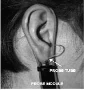
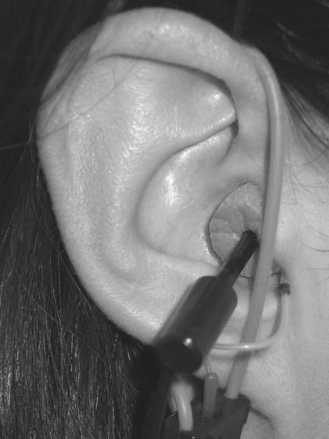
Figure 9. Setup for the real-ear-to-coupler difference (RECD) measurement on the Audioscan showing placement of the probe tube/probe module (left) and subsequent insertion of the foam ear tip (right).
Why should you do it? (RECD)
The RECD is a powerful tool that can assist the clinician throughout the various stages of the amplification process. For instance, the RECD allows you to accurately convert assessment information collected with insert phones from dB HL to dB SPL (Scollie et al., 1998b) by, in effect, adjusting the 2cc coupler calibration values used with insert phones. This is helpful when using hearing instrument fitting methods that use the SPL-O-GRAM format (e.g., DSL). RECD values can also be used to convert real-ear targets to 2cc coupler targets to assist with selection of hearing instruments via manufacturers' specification sheets.
Arguably the most useful application of the RECD is in the prediction of real-ear output when measuring hearing instruments in the 2cc coupler. Given that the RECD allows us to know the difference between output in the real-ear and the 2cc coupler, real-ear hearing aid output (e.g., REAR, RESR) can be accurately predicted to within approximately 2 dB (Seewald et al, 1999).
The ability to predict hearing instrument output offers a number of advantages, which, as described by Seewald (1997) include the following:
1. The audiologist will know the levels of amplified sound delivered into the patient's ear canal.
2. The unique acoustic properties of the ear and earmold coupling (if the RECD is conducted with the earmold) will be accounted for. This helps avoid errors that can occur when using average values in the fitting process.
3. All hearing instrument response shaping can be performed in the hearing aid test chamber, under highly controlled acoustic conditions.
4. The degree of cooperation and amount of time required from the patient in the fitting process is greatly reduced.
Complete details of the rationale for and application of the RECD is provided in Moodie et al. (1994).
G. REDD (Real-Ear-to Dial Difference)
What is it?
- Formal Definition: Difference in decibels, as a function of frequency, between the SPL at a specified measurement point in the ear canal and a specified audiometer dial setting. Note: ANSI S3.46-1997 does not define REDD.
- Informal Definition: Difference in dB, across frequencies, between the SPL measured in the real-ear and the audiometer dial setting that produced it.
An example of a typical REDD is shown in Figure 12 below. The measured REDD values, as a function of frequency should generally be greater than 0 dB. As can be expected, REDD values can vary substantially across individuals (Valente et al., 1994). A negative REDD may indicate an inadequate seal of the transducer to the ear, blocked probe tube or improper probe tube placement.
How is it done? (REDD)
A number of real-ear equipment manufacturers have incorporated automated REDD measurement procedures into their software. Check with the manufacturer for specific instructions on how to conduct this measurement with the equipment you are using.
The typical steps, with an emphasis on the Audioscan RM500 implementation, are outlined below.
- Conduct otoscopic examination.
- Place probe tube in the ear canal, with end of tube at the appropriate distance from the intertragal notch (i.e., within 5 mm of the eardrum).
- Place the same style of earphones used during the audiometric assessment over the patient's ears, being careful not to move the inserted probe tube.
- Set the audiometer dial setting to a desired frequency (e.g., 250 Hz) and present a 70 dB HL continuous tone from the audiometer.
- Measure the output in the ear canal.
- Subtract the audiometer dial setting (e.g. 70 dB HL) from the real-ear measurement (e.g., 80 dB SPL) to obtain the REDD for that frequency. (Most equipment will calculate the REDD automatically for you).
- Continue on and repeat the same process until REDD values have been obtained at all desired frequencies.
Why should you do it? (REDD)
The REDD is used to convert audiometric information (e.g., thresholds and uncomfortable listening levels) from dB HL format to dB SPL format. That is, the REDD will allow the audiologist to construct SPL-O-GRAMS for use with hearing aid fitting methods that take this approach (e.g., DSL). As you will recall from our earlier discussion, the RECD can also be used to transform audiometry from dB HL to dB SPL when insert phones have been used in the assessment. Clinically the REDD is used primarily when headphones have been used for audiometry. This conversion approach has been determined to be accurate within approximately 2.3 dB of the true real ear SPL (i.e., the level that would have been measured at the eardrum had a probe tube been placed there during audiometry) (Scollie et al., 1998b).
H. RESR (Real-Ear Saturation Response)
What is it?
- Formal Definition: SPL, as a function of frequency, at a specified measurement point in the ear canal, for a sound field sufficient to operate the hearing instrument at its maximum output level, with the hearing aid (and its acoustic coupling) in place and turned on, with the gain adjusted to full-on or just below feedback. Note: ANSI S3.46-1997 does not define RESR.
- Informal Definition: The frequency response of a hearing instrument, measured in the ear canal, with an input signal sufficiently intense to operate the hearing instrument at its maximum output level. Also may be described as an REAR with an input signal loud enough to operate the hearing instrument at its maximum output level.
How is it done? (RESR)
- Conduct otoscopic examination.
- Place probe tube in the ear canal, with end of tube at the appropriate distance from the intertragal notch (i.e., within 5 mm of the eardrum).
- Insert the hearing instrument into the client's ear while holding the probe tube so that its position in the ear canal is not disturbed.
- Turn the hearing instrument on and set user gain control to the highest position before feedback or to the projected use setting.
- Select an input signal loud enough to operate the hearing aid at its maximum output level (e.g., 90 dB SPL pure tone/warble tone signal).*
- Conduct the measurement.
*Note: Given the potential for high sound levels in the ear canal, it is prudent to preset the maximum output of the hearing instrument in the coupler (using the RECD to predict real-ear output) to avoid exceeding uncomfortable loudness levels. If this is not possible, begin the RESR measurement with the OSPL90 control on the hearing instrument set to minimum.
*Note: RESR values can vary substantially depending on the input signal used, with narrow band signals (i.e., pure tones/warble tones) typically providing a better estimate of worst case possible output than broad band signals (i.e., white noise, speech shaped noise) (Stelmachowicz et al, 1990).
Why should you do it? (RESR)
The primary purpose of the RESR is to determine the maximum SPL that the hearing aid is capable of delivering to the user's ear. This information can be used to adjust the maximum output capabilities of the hearing instrument to ensure that amplified signals do not exceed uncomfortable listening levels during everyday use. It also allows the audiologist to determine whether the maximum output setting of the hearing instrument is overly restrictive (i.e., determine whether adequate headroom is available for loud signals). Given the possibility of discomfort during this measurement, however, it is preferable to predict the RESR via coupler measurements and the patient's RECD. See Seewald (1991) or Hawkins (1992) for more information regarding hearing aid output limiting considerations.
Summary
Despite the continued advancement in hearing instrument technology, the need to determine what is actually occurring in the ear's of our patients while they are wearing hearing instruments remains. Unless we conduct objective measurements, we cannot be certain that the hearing instrument is performing the way we want (or expect) it to based on the auditory needs of the patient we are fitting. The aforementioned procedures, when conducted appropriately, will provide you with useful information throughout the amplification process.
References
American National Standards Institute. (1997). Methods of Measurement of Real-Ear Performance Characteristics of Hearing Aids. ANSI S3.46-1997. New York: American National Standards Institute Inc.
Dirks, D., Kincaid, G. (1987). Basic acoustic considerations of ear canal probe measurements. Ear and Hearing, 8 (Suppl. 5), 60S-67S.
Feigin, J., Kopun, J., Stelmachowicz, P., Gorga, M. (1989). Probe-tube microphone measures of ear canal sound pressure levels in infants and children. Ear and Hearing, 10(4): 254-258.
Hawkins, D. (1992). Selecting SSPL90 using probe-microphone measurements. In Mueller, Hawkins, Northern (eds.): Probe Microphone Measurements: Hearing Aid Selection and Assessment. (pgs. 145-158). San Diego, CA: Singular Publishing Group Inc.
Hawkins, D., Alvarez, E., Houlihan, J. (1991). Reliability of three types of probe tube microphone measurements. Hearing Instruments, 42: 14-16.
Hawkins, D., Mueller, H. (1986). Some variables affecting the accuracy of probe tube microphone measurements. Hearing Instruments, 37(1): 8-12, 49.
Hawkins, D., Mueller, H. (1992). Procedural considerations in probe-microphone measurements. In Mueller, Hawkins, Northern (eds.): Probe Microphone Measurements: Hearing Aid Selection and Assessment. (pgs. 67-90). San Diego, CA: Singular Publishing Group Inc.
Ickes, M., Hawkins, D., Cooper, W. (1991). Effect of reference microphone location and loudspeaker azimuth on probe tube microphone measurements. Journal of the American Academy of Audiology, 2: 156-163.
Martin, H., Munro, K., Langer, D. (1997). Real-ear to coupler differences in children with grommets. British Journal of Audiology, 31(1): 63-69.
Moodie, K., Seewald, R., Sinclair, S. (1994). Procedure for predicting real-ear hearing aid performance in young children. American Journal of Audiology, 3: 23-31.
Mueller, H. (1992). Terminology and Procedures. In Mueller, Hawkins, Northern (eds.): Probe Microphone Measurements: Hearing Aid Selection and Assessment. (pgs. 41-66). San Diego, CA: Singular Publishing Group Inc.
Mueller, H., Hawkins, D., Northern, J. (1992). Probe Microphone Measurements: Hearing Aid Selection and Assessment. San Diego, CA: Singular Publishing Group Inc.
Preves, D., Sullivan, R. (1987). Sound field equalization for real-ear measurements with probe microphones. Hearing Instruments, 38: 20-26, 64.
Scollie, S., Seewald, R., Cornelisse, L., Miller, S. (1998a). Procedural considerations in the real-ear measurement of completely-in-the-canal instruments. Journal of the American Academy of Audiology, 9: 216-220.
Scollie, S., Seewald, R., Cornelisse, L., Jenstad, L. (1998b). Validity and repeatability of level-independent HL to SPL transforms. Ear and Hearing, 19(5): 407-413.
Seewald, R. (1991). Output limiting considerations for children. In Feigin and Stelmachowicz (eds.), Pediatric amplification: proceedings of the 1991 National Conference (pgs. 19-36). Boys Town National Research Hospital Press.
Seewald, R. (1997). Amplification: a child-centered approach. Hearing Journal, 50(3): 61.
Seewald, R., Moodie, K., Sinclair, S., Scollie, S. (1999). Predictive validity of a procedure for pediatric hearing instrument fitting. American Journal of Audiology, 8: 143-152.
Stelmachowicz, P., Lewis, D., Seewald, R., Hawkins, D. (1990). Complex and pure-tone signals in the evaluation of hearing aid characteristics. Journal of Speech and Hearing Research, 33: 380-385.
Storey, L., Dillon, H. (2001). Estimating the location of probe microphones relative to the tympanic membrane. Journal of the American Academy of Audiology, 12(3): 150-154.
Tecca, J. (1994). Use of Real-Ear Measurements to Verify Hearing Aid Fittings. In Valente (ed.): Strategies for selecting and verifying hearing aid fittings (pgs. 88-107). Thieme Medical Publishers Inc., New York.
Valente, M., Potts, L., Valente, M., Vass, W., Goebel, J. (1994). Intersubject Variability of Real-Ear Sound Pressure Level: Conventional and Insert Earphones. Journal of the American Academy of Audiology, 5(6): 390-398.