Learning Outcomes
After this course, participants will be able to:
- Describe the rationale for the DSL-BCD prescriptive targets, used with bone anchored hearing devices.
- Describe the studies used to develop and revise the DSL-BCD prescriptive targets.
- Summarize the main steps of a fitting protocol designed for use with the Audioscan Verifit skull simulator.
In this course, we will review recent work to develop a prescription for use with bone conduction hearing devices and associated verification techniques for these instruments on a coupler-like device called a Skull Simulator. Prescription and verification of air conduction hearing aids is well understood. This course will discuss whether we need prescription and verification tools for bone conduction hearing aids. First, we will consider the rationale and evidence behind prescription and verification with air-conduction hearing aids.
Prescription/Verification for Air Conduction Hearing Aids
Prescription and verification help us achieve consistent and beneficial levels of audibility across patients with air conduction hearing aids (McCreery, Bentler, & Roush, 2013; McCreery, Brennan, Walker, & Spratford, 2017; Moodie, Scollie, Bagatto, & Keene, 2017). Prescriptions are designed for use with nonlinear signal processing such as wide dynamic range compression. Modern air conduction prescriptions can work accurately with nonlinear devices because they are built on well-defined and realistic speech signals (Holube, Fredelake, Vlmaing, & Kollmeier, 2010) and use speech-based nonlinear input/output target functions (Scollie et al., 2005). We verify and fine tune to match prescriptive targets with high quality, speech-based test signals. Verification measurements capture the aided speech spectrum, and the range of aided speech as percentiles (sometimes called peaks and valleys). Using these tools, the aided levels of speech displayed on the verification system are valid measurements, regardless of whether or not the hearing aids are linear or nonlinear. In recent years, bone conduction devices moved to more nonlinear signal processing. Therefore, as with air conduction devices, it may be better to adjust and fit bone conduction hearing devices with speech-based verification (rather than with aided warble-tone thresholds). A 2010 study compared aided thresholds versus suprathreshold aided speech verification with bone conduction hearing devices. The results indicated that it's more fruitful to use suprathreshold verification of aided speech, if we are interested in measuring device performance for realistic input levels (Hodgetts Hagler, Håkansson, & Soli, 2010). In summary, one thing that air conduction and bone conduction hearing aids have in common is that assessing their performance for speech is best done with speech input test signals.
Prescription and Verification Improve Consistency of Fittings Across Patients
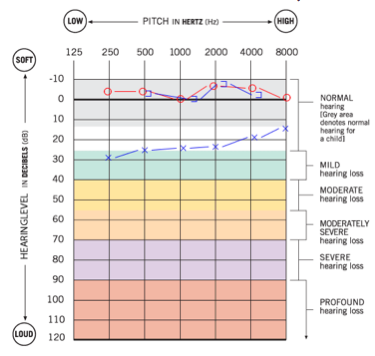
We know from large-scale studies of children who use air conduction hearing aids that the consistency in verification protocols is important. If we look at data for children with different degrees of hearing loss as measured by pure tone average and consider the Speech Intelligibility Index (SII), which is the proportion of speech that is available to the child, we know that protocols matter (Moodie et al., 2016). Moodie and colleagues looked at data from a set of clinics that all followed a common practice; they routinely verified the aided levels of speech and fit to target. The data show that children received similar levels of aided speech audibility even though they were seen at different clinics. We can contrast that to another recent study that looked at children who were fit at a wide range of clinics who followed different protocols (McCreery et al., 2015). In this case, some clinics reported conducting verification, and others did not report routinely verifying hearing aids (or not measuring the child's real-ear-to-coupler difference, for example). There were a variety of clinical practices reported, and also a variation in outcomes. Some children received high and consistent levels of speech audibility where other children did not. For example, a child who has a 60 dB pure tone average (PTA) could be expected to have an SII of 70 to 80%. In this study, some children with a 60 dB PTA had an SII as low as 40% or even 20%, both of which are unacceptably low. To avoid this problem for particular children, the main tool we have is to choose a validated prescriptive target and routinely verify the fitting on every child. Then, it is important to check the fitting at regular intervals as the child grows and matures, as their ear canal acoustics and hearing loss change. This is well established as preferred (best) practice for air conduction hearing aids.
Prescription and Verification Impact Audibility of Specific Speech Sounds
High quality hearing aid fittings that provide audibility of a broad bandwidth provide access to specific speech sounds. Two recent studies using air conduction hearing aids highlight this point (McCreery, Brennan, Walker, & Spratford, 2017; Scollie et al., 2016a). McCreery and colleagues (2017) looked at children's hearing aid fitting data to see if deviations from prescriptive targets impacted speech recognition in quiet and in noise. In other words, if children have good fittings, particularly in the high frequencies, does it affect speech recognition? They found that children who had lower sensation levels, and therefore poorer audibility of speech at 4 kHz, also had poorer speech recognition in quiet and poorer speech recognition in noise. The results indicated that children whose hearing aids were fitted to provide audibility across a wide range of inputs and frequencies had better speech recognition outcomes. Clinically, this means that verification and fine tuning of frequency response shape may be an important precursor to hearing aid benefit. A related idea is the use of specific speech sounds to crosscheck the fitting. For instance, we have developed methods for evaluating frequency lowering signal processing that include verification with a simulation of the speech sound "s" (Scollie et al., 2016a). This allows us to look at whether or not the high frequency component of the hearing aid fitting is providing access to that particular speech sound. These studies highlight the rationale for having hearing aid verification tools to assess the frequency responses of fittings for speech. In fitting air conduction hearing aids, the DSL Method displays the prescriptive targets, hearing aid output, and patient thresholds on one display called the SPLogram to facilitate interpretation of audibility.
Verification Systems Allow Us to Compare and Document the Impact of Signal Processing and the Effectiveness of Accessories
There is a reason to use our verification approaches to compare and document the impact of signal processing and the effectiveness of accessories. In one study, we observed that the activation time and the activation strength of noise reduction systems varied significantly across brands and settings in commercial hearing aids (Scollie et al., 2016b). Because of this, in our current protocols we emphasize the importance of the fitting audiologist knowing the activation speed and strength of the processor. Similarly, feedback managers are not all created equal. Some feedback managers affect the frequency response and others do not. Remote microphone and streaming devices can have connection issues or breakdown – without electroacoustic measurements it can be challenging to diagnose or document these problems. We know that hearing aid analyzers provide good objective solutions for addressing these particular technologies, but they've only been available for use with air conduction hearing aids until recently.
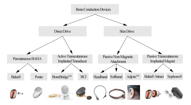
Bone Conduction Devices: Types and Terminology
There has been a lot of evolution, change and development in bone conduction devices in recent years. There are four families of bone conduction devices as shown in Figure 1: those that are worn and coupled to an abutment (percutaneous bone anchored hearing aid (BAHA); also referred to as percutaneous bone anchored hearing devices (BAHD); those that are fully implanted (active transcutaneous implanted transducer); those that send the signal through the skin with a headband system (passive non-magnetic attachment); and, those that use an implanted magnet (passive transcutaneous implanted magnet). Today's presentation focuses on percutaneous bone anchored hearing devices (BAHD). Percutaneous devices are those that are worn on a surgically implanted, bone-anchored abutment. There are several different brands and models of devices that fall into this particular category.
Is it Possible to Verify Bone Conduction Hearing Aids?
Many clinicians are familiar with the probe tube microphone systems and air conduction coupler microphone sets that are used for measuring the output of air conduction hearing aids. For measurement of bone anchored hearing devices, an invention called a skull simulator has been available for some time. A research-grade skull simulator (TU-1000) was developed by Håkansson and Carlsson in 1989, and has been used extensively, in research studies. It wasn't designed or commercially produced as a clinical tool, but it has been used in research labs and in industry. The skull simulator is analogous to a coupler microphone. The bone anchored hearing device is attached to the abutment of the skull simulator. The bone anchored device vibrates in response to sound and delivers the force output that it generates into the skull simulator, which is connected to a measurement device. This allows measurement of the aided output of the bone anchored hearing aid, much like making a coupler measurement for air conduction hearing aids.
Additionally, an on-head microphone is in early development (Hodgetts, Scott, Dylan, Maas, & Westover, 2018). It is at a research stage right now, so it is not yet available for clinical use. It is analogous to a probe microphone. With this on-head microphone, it may be possible to verify levels of aided speech or other signals from a wider variety of bone conduction hearing systems.
Verification Lessons from the Lab
Audibility and Bandwidth Matter, Just Like with Air Conduction Hearing Aids
One thing that we have learned is that just like with air conduction hearing aids, audibility and bandwidth matter. Earlier, we reviewed research by McCreery et al. (2017) revealing that the actual levels of audibility and the bandwidth fitted via an air conduction hearing aid affected the benefit from those devices. Hodgetts and colleagues found similar results using abutment-worn, bone conduction devices (Hodgetts, Hagler, Håkansson, & Soli, 2011). In their study, each participant performed speech recognition tasks using two different bone anchored fittings. They measured the output of the abutment-worn device as a function of frequency. They plotted the patient's thresholds alongside the verified results. This type of display is similar to the SPLogram that we use in fitting air conduction hearing aids. In the study, they provided one fitting type that had an aided speech spectrum that peaked in the mid-frequencies, and rolled off in the low frequencies and high frequencies. The alternative fitting used a research device to provide a flatter, broader frequency response with more high frequency gain and improved high frequency audibility.
The participants performed speech recognition tasks with both fittings, and had better results with the fitting that provided better high frequency audibility. This study indicates that for users of bone anchored hearing devices, optimization of benefit is about more than just providing the hearing devices. Just as with air conduction hearing aids, it is important to fit a device that has been fine-tuned, adjusted, and verified to provide that individual with an appropriate and optimized amount of audibility across frequencies. That really comes down to prescription and verification.
Bone Anchored Devices: Responses on the Head Versus on the Coupler
Just like with air conduction hearing aids, bone conduction devices have a different response when worn than they do on the coupler. With air conduction hearing aids, the real-ear-to-coupler difference (RECD) is measured across frequencies and represents the difference of the output in the ear versus in the coupler. From many normative studies we know that earmold RECDs have a mid-frequency boost compared to foam-tip RECDs, and we know how this varies across ages. We use this knowledge in our prescription and verification as a transform, especially to generate age-predicted RECDs when measured values are not available (Bagatto et al., 2005). A similar issue exists for bone anchored hearing devices. With bone anchored hearing devices, there is a real-head-to-coupler difference (RHCD) (Hodgetts et al., 2018). The RHCD is the difference between the device's response when it is worn on the patient’s abutment versus when it is on the skull simulator. It has a different shape than an RECD, but conceptually is similar to an RECD. In the prescription and verification method discussed below, the RHCD is equivalent to an RECD and is used in similar ways.
A Complete Fitting Screen Requires Force Level Thresholds
When fitting air conduction hearing aids, we use the SPLogram to display thresholds and hearing aid targets and responses on a common scale. This display requires that we convert thresholds from hearing level (HL) to sound pressure level (SPL) to get everything in the same measurement scale. For bone conduction hearing aids, we often test people's hearing first by bone conduction using an audiometric bone conduction oscillator. A bone conduction oscillator sends the output signal through the skin and subcutaneous tissue between the oscillator and the skull. We can contrast that with direct bone conduction, which sends vibration through the abutment directly into the bone of the mastoid. Conduction through an abutment is more "direct" than through skin, so audiometric bone thresholds don't necessarily equal direct abutment-based thresholds.
Verstraeten and colleagues (2009) compared thresholds obtained via transcutaneous hearing (i.e., thresholds measured using a bone oscillator) to thresholds via percutaneous hearing (i.e. thresholds measured through an abutment). Their data show that as frequency increases the differences generally increase, and the difference is fairly large in the region of 3000 - 6000 Hz. The research also shows some individual variability, with some individuals showing greater differences than others. For developing a fitting and verification display, this is an important issue. Generally, the fitting display will be most accurate if the user's thresholds are displayed as measured through the abutment, so that they are directly relevant to hearing with the abutment-worn devices. This leads into the concept of direct bone conduction audiometry, discussed below.
Loudness Growth in Bone Conduction Hearing is Different Than in Air Conduction Hearing
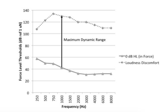
Another component we considered from research studies is loudness growth. To develop a complete prescription, we need to have data on how loud people judge sounds to be, from ‘inaudible’ to ‘very loud’ to ‘too loud’. In air conduction prescription, we know how loudness growth is affected by sensorineural hearing loss. For bone conduction hearing, Stenfelt and Zeltooni (2013) demonstrated that some differences exist that may be important for understanding loudness growth. They compared air conduction and bone conduction loudness across presentation levels. They found that loudness grows a little more rapidly for bone conduction hearing than for air conduction hearing. This means that the size of the dynamic range of hearing predicted in a prescriptive method needs to account for this difference in loudness growth.
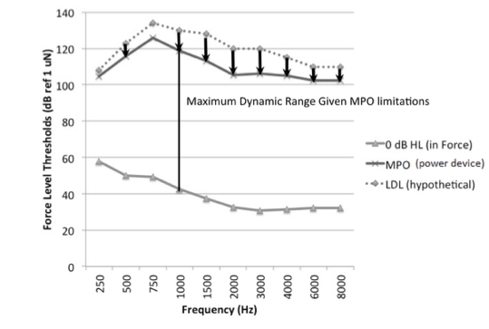
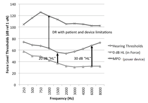
The Biggest Limiting Factor in Bone Conduction Hearing is the Output Limiting of the Device, Not the User’s Loudness Discomfort Levels
In air conduction hearing aid prescription, we plot the listeners expected upper limits of comfort onscreen so that the aided levels of sound can be evaluated against them: we try to avoid amplifying sound above this level. A challenge with bone conduction hearing devices is that the output limiting of the device may be significantly lower than the predicted upper limits of comfort. Also, maximum output force levels vary considerably across devices. Our recent data showed there was more than 20 dB variation in maximum force level output among devices we tested (Hodgetts & Scollie, 2017). Unlike air conduction fittings, the reality for bone conduction fittings is that the major limiting factor will be the device, not the user’s hearing. Therefore, the implication for the DSL bone conduction prescription is that the maximum output targets change with device make and model. With prescriptive targets, we are trying to map a wide range of sounds into the listener's dynamic range. We may use nonlinear signal processing to compress the amplified signals into a smaller output range. Nonlinear prescriptive targets implement this to create level-dependent prescriptive targets. In the case of bone conduction hearing, we can use compression to try to fit a wide range of inputs into the individual's range of hearing, taking into account the actual maximum output of the device.
In summary, our goal was to create a set of prescriptive targets that takes all of these lessons from research and incorporates them into a clinically usable method for fitting and verifying bone conduction hearing aids that can be embedded into commercial hearing aid fitting systems.
DSL for Bone Conduction Devices (DSL-BCD): Development of Version 1.1
FLogram
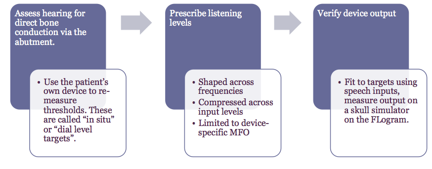
This defines a series of steps to follow in clinical practice, and protocols that define key measurements to make. Step one is assessing the hearing for the patient via their abutment. Using the patient's own device, we measure the direct bone-conduction thresholds so that they incorporate how the device responds on the head of the individual patient. These in-situ thresholds are measured as dial-levels measured via the device-specific programming module. The dial levels then get converted through the DSL prescriptive software to force levels on the abutment.
In step two, we compute prescribed targets for speech that are recommended listening levels for that particular patient. The targets will be shaped across frequencies, compressed across input levels, and will be limited to the device-specific maximum force output. In step three, we verify the output of the device (e.g., via a skull simulator), using a speech signal as the input. We assess the fit to targets on the FLogram. We fine-tune the device as needed to optimize the fit to target, and interpret the audibility of the hearing aid fitting by comparing the aided speech frequency responses to the force level thresholds of the device user.
This clinical workflow is similar to the workflow used with air conduction devices. The key differences with bone conduction devices are: (1) we measure the thresholds in-situ with the device on the abutment using the programming module, and (2) we verify the device when connected to a skull simulator.
First Version of DSL-BCD Targets
In developing the DSL-BCD method, we based the first version of DSL-BCD targets on DSL v5. We started by only applying the transforms necessary to convert DSL v5 from dB SPL to dB FL. This meant that the target shaping and audibility goals were the same as for air conduction hearing aids, with the exception of the loudness and dynamic range adjustments described above. An example of this early target is shown in Figure 6. The targets used wide dynamic range compression, mainly to overcome the limited output dynamic range of the devices. Similar to DSL v5, the DSL-BCD version 1 targets had more gain and output for children; frequency shaping for audibility; a slight reduction for binaural fittings in adults; and targets that fall below threshold for very low input levels, especially if they are below compression thresholds. The targets are, in many ways, similar to DSL air conduction targets.
We completed a validation study to assess the DSL-BCD v1 target. We compared the targets to the actual levels of aided speech used by 39 successful percutaneous bone-anchored device users with a wide range of hearing levels. These adults were fitted at the iRSM clinic in Edmonton, Alberta, Canada. The fittings were completed in a clinic that has a large patient case load that specializes only in fitting this device category, and that monitors the outcomes of their patients.
They were regular wearers of their devices, using them for at least eight hours per day for at least two months, so they were highly acclimatized listeners. Each user’s hearing aid was measured at their own user settings. Measures were made using running speech as an input, for a test level of 65 dB SPL. We used the ISTS signal (Holube et al., 2010) and filtered it to include microphone location effects appropriate for bone-anchored hearing aids, on a research skull simulator. We compared the measured output to the DSL-BCD v1 targets for each patient.
In the high frequencies, we found that high frequency targets and fittings were not significantly different. In the mid-frequencies, the measured device outputs and targets were fairly close, with a 4 dB difference on average. This difference showing mid-frequency targets to be slightly higher than the typically worn values was attributed to an unwanted resonance in the device that could not be resolved with fine tuning. However, in the low frequencies, targets were 19 dB higher than where the successful users actually wore their devices. This was attributed to a necessary fine-tuning change to fit the devices to the user’s preferences.
Considering all of these results, low frequency targets required further adjustments. An adjustment was therefore built into the frequency shaping of the DSL-BCD algorithm to better approximate the preferred frequency response of these users, while the audibility of the mid- and high-frequency targets was maintained at the originally prescribed levels. In summary, the difference between DSL-BCD v1.0, which was the preliminary version, and v1.1, which is the version that is available now, is this low-frequency adjustment. The modified v1.1 target agrees with the fittings of the 39 patients within less than two dB across frequencies.
We also evaluated the aided Speech Intelligibility Index (SII) values for these fittings. These data indicate that these users had high and consistent SII values that vary with the degree of hearing loss. The SII values vary between 75% to about 95% when the four-frequency pure-tone average is about 60 dB or less, and decline as the hearing losses exceed this level. This overall pattern of SII varying with degree of hearing loss is consistent with SII trends with air conduction fittings (Moodie et al., 2017).
Applying DSL-BCD v1.1 in Clinic with the Audioscan Verifit Skull Simulator
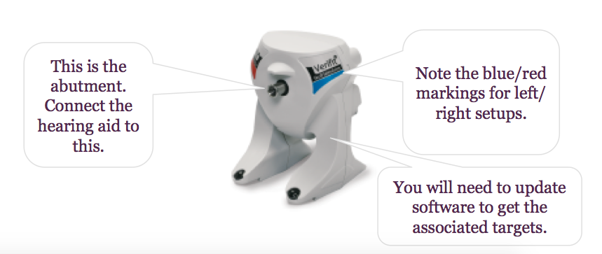
As a practical tip, remember to ensure that the air conduction microphones in the test box have been calibrated before moving to the skull simulator. This step is necessary to ensure that the reference microphone(s) in the test box, which will still be used for bone conduction device testing, are calibrated and functioning correctly. After completing this step, unplug the air conduction coupler microphone(s) and plug the skull simulator into the coupler microphone jack in the test box (Figures 8 and 9), shown for both Verifit2 (VF-2) and Verifit1 (VF-1).
It's important to position the skull simulator correctly. Position the skull simulator sideways to the test box speaker, so that the front facing microphone on the bone conduction device is directly facing the speaker. Depending on the device side you are testing, orient the skull simulator so that the red marking is facing you when verifying right devices and the blue marking is facing you when verifying left devices. This placement procedure is shown in Figure 8 and can also be found in photos located within the ‘Help’ system integrated into the Verifit. Note that with the Verifit1 system, the skull simulator is too tall to allow the lid to close, so running tests in a quiet room is essential. After set up, you can run quality control tests, coupler tests, manual control tests, or adjust fittings to targets.
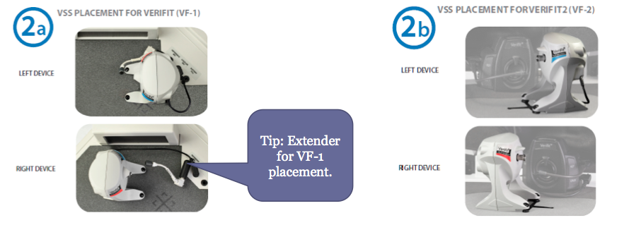
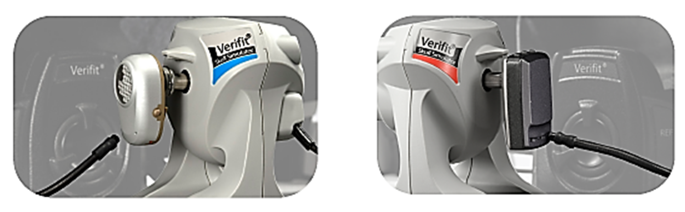
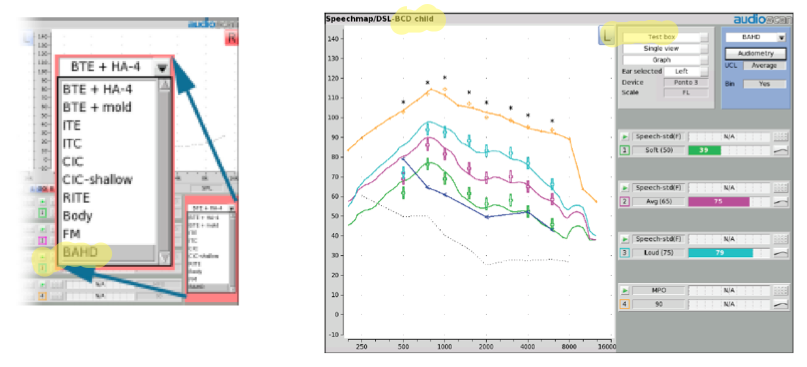
Figure 10 shows the menu that appears after you've selected bone anchored hearing devices (BAHD) as the hearing aid type. Selecting "BAHD" indicates to the software to move into bone conduction fitting mode, and to use the skull simulator for measurement rather than the air conduction coupler microphones. At that point, you will see DSL-BCD for the bone-conduction prescription in the upper left corner of the fitting screen, so you know that you're working in the skull simulator verification mode.
Clinical Cases
Case 1
Case 1 is a 65-year-old male, with a history of bilateral chronic ear disease with multiple tubes and bilateral mastoidectomies. This patient became a candidate for an abutment-worn solution, and was implanted in 2013. He has been a long-standing user of abutment-worn hearing devices. His audiometric information is shown in Figure 11, however, we did retest his hearing by direct bone conduction using the hearing aid fitting software and the device worn in-situ. This process tests through the abutment to remove any effects of conduction through skin and other tissue. The direct thresholds, not the thresholds from the audiogram, are the ones entered into the software.
We would customize the targets for this case as shown in Figure 12. We chose DSL-BCD-adult rather than the child prescription, based on the patient's age. Next, we selected the device make and model that we are fitting. The patient had recently updated to a new device, and that was the reason for the refitting. Remember, selecting the device make and model defines the maximum output target. On the left in Figure 13 is the FLogram. The line closest to the bottom is a normal set of thresholds that is equivalent to zero dB HL, but as measured through an abutment. This patient has a slight threshold elevation relative to that, as depicted by the red line. The patient’s targets are shown in Figure 13 for maximum output (orange symbols) and for three levels of speech ranging from 55 through 75 dB SPL (green, pink, and blue symbols).
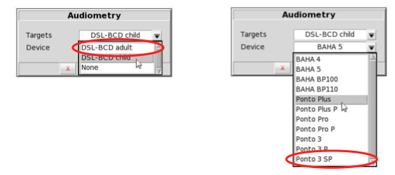
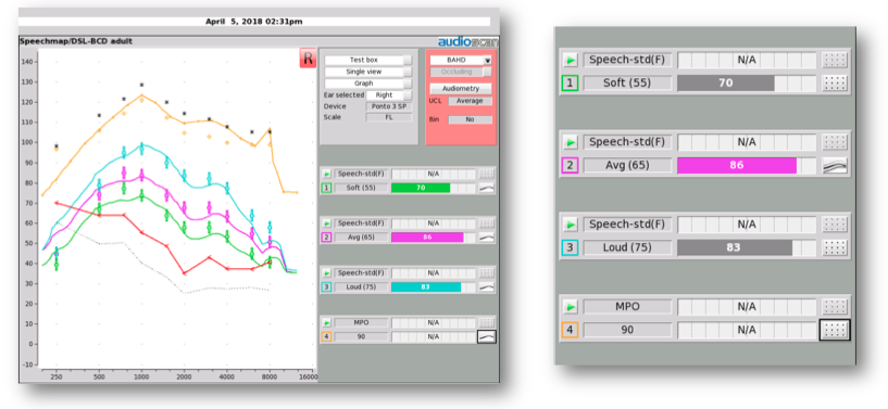
Figure 13. Fitting results for case 1.
This close fit to targets resulted from connecting the hearing aid to the fitting software, fitting, and fine tuning. On the right side of Figure 13 are the SII values: the aided spectrum for an input of speech at 55 dB SPL has an SII of 70%; 65 dB speech has an SII of 86%; and 75 dB speech has an SII of 83%. These high SII values are consistent with what see on the fitting screen, which is that the speech is audible across a broad range of frequencies, and has been set to appropriate listening levels. The aided SII values are also similar to the published values observed in the Hodgetts & Scollie (2017) study ( >70% would be expected).
Beyond fitting to target, we can also use the system to assess the noise reduction and directionality of the hearing aid. First, let’s consider directionality of bone conduction devices. Figure 14 shows two sets of output across frequencies: output for sounds that are mostly coming from the front, and output for sounds that are mostly coming from the rear. If there's a difference between these two, shown as a separation of the curves in Figure 14, it indicates that the hearing aid is attenuating sounds from the back (i.e., it is directional). This type of test lets you assess the directionality of a hearing aid across settings, across devices, and over time.
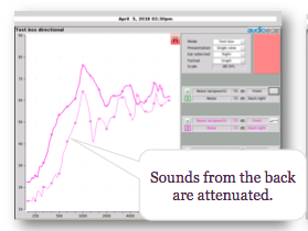
Figure 14. Directional test in full band mode.
Similarly, we can look at noise reduction by running a noise reduction test, as shown in Figure 15. This set of tests compares the same hearing aid, tested with its noise reduction programmed to be either off or on. For both settings, the heavier spectrum (i.e., thicker line) is the response of the device at the beginning of the test, and the lighter one (i.e., thinner line) is the response at the end of the test. The right panel shows results with noise reduction off. In this test, the slight differences in the curves are not significant differences. The left panel test with noise reduction on shows that after 30 seconds, the device has attenuated its frequency response. In other words, this signal processor can reduce this noise signal. On average, this device provided about 10 dB of noise reduction. You can use this test to make comparisons across settings in the same hearing aid, across hearing aids, and objectively assess the differences in the signal processing. Like the directional test, this noise reduction test allows you to characterize what type of signal processing you are using. In air conduction hearing aids, we see a lot of variability in signal processing across settings and across brands.
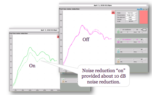
Figure 15. Noise reduction test with off versus on.
Case 2
Case 2 is an eight-year-old girl with unilateral atresia and microtia. She has been a successful softband user, and she recently received an implant and an abutment-worn device. She has normal hearing thresholds by direct bone conduction, and normal hearing thresholds by an audiometric bone oscillator, as shown in Figure 16.
This patient’s direct bone-conduction thresholds were entered into the fitting system. We customized the targets to be child targets (DSL-BCD child), and we selected the specific hearing aid make and model that she was using so that the maximum force level targets would be appropriate for her fitting. Her previously-worn bone-conduction hearing aid was convertible for use on her abutment, so the main purpose of this visit was to re-adjust the device for use via direct bone conduction.
Her fitting results are shown in Figure 17. We were able to meet targets for maximum output and for three levels of speech. In this case, the aided SII values range between 87 and 94%, which is similar to the SII that we would expect for someone with normal hearing or an aided mild hearing loss, if hearing by air conduction. These values are somewhat higher than the aided SII values we observed for the adult case discussed previously, which is consistent with adult-child differences in SII for air conduction hearing aid fittings.
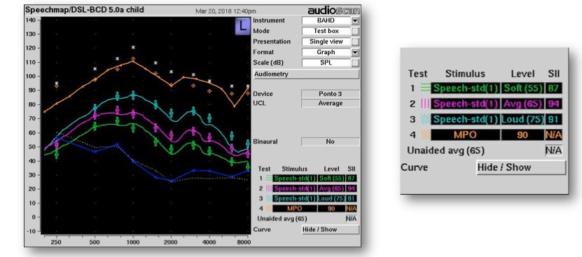
Figure 17. Results, case 2.
If we were continuing with this case, we could do other things in the fitting software and verification system. For example, if she uses a remote microphone system to support listening in the home or in the classroom, we could verify that it is successfully connecting into and transmitting sound via the bone-conduction device. To do this, we would place the remote microphone in the test box, wirelessly connect it to the bone-conduction device, and measure the output of the combined system on the skull simulator.
Softband Fittings
This course mainly addresses a prescription and verification approach for bone-anchored, or percutaneous, hearing aids. We haven't yet completely adapted this particular system further for devices worn on headbands or other mechanisms for bone-conducted hearing. Certainly, there are modality-specific differences and there would have to be adjustments to the transforms and prescriptive targets described here to support clinical use with other device categories. That said, we know that it is possible to measure headband-worn devices on an artificial mastoid (Hodgetts, Scollie, & Swain, 2006) so it is possible to develop a clinical procedure that could work with a commercially-available skull simulator. Until a full solution is available, we recommend that any measures with headband devices not be considered as prescriptive but rather as more descriptive of what successful fittings might look like.
Summary
Today's key points can be summarized as follows:
- Clinical skull simulators are now available for several types of hearing aid analyzers. The Verifit skull simulator supports ANSI, DSL-BCD targets, and analysis of signal processing.
- The verification steps with bone anchored hearing devices are pretty similar to fitting air conduction hearing aids. A few minor differences in transforms and the role of device-specific maximum output are reviewed in this course.
- Audioscan skull simulators can be moved between units and between the Verifit 1 (serial numbers 2070 and higher) and Verifit 2.
- Remember to calibrate the air conduction microphones first (weekly) before connecting the skull simulator.
- Remember to learn the left/right positioning & place the reference microphone within 1-3 mm of the hearing aid microphone. Check the Verifit ‘Help’ menu for photos of setups and further instructions.
References
Bagatto, M., Moodie, S., Scollie, S., Seewald, R., Moodie, S., Pumford, J., & Liu, K.R. (2005). Clinical protocols for hearing instrument fitting in the Desired Sensation Level method. Trends in Amplification, 9(4), 199–226.
Carlsson, P., & Håkansson, B. (1997). The bone-anchored hearing aid: Reference quantities and functional gain. Ear Hear, 18, 34–41.
Citation
Scollie, S., Hodgetts, W.E, & Pumford, J. (2018, June). DSL for bone anchored hearing devices: Prescriptive targets and verification solutions. AudiologyOnline, Article 22962. Retrieved from www.audiologyonline.com