
Editor's note: This text course is an edited transcript of an Audioscan webinar on AudiologyOnline. An Internet connection is required to view several videos that demonstrate the measurements discussed in the course.
Learning Outcomes
After this course, participants will be able to:
- Explain how to implement an electroacoustic test procedure that verifies transparency of FM systems.
- Demonstrate how to conduct an on-ear test of FM systems to verify target attainment and aided speech audibility.
- Describe how to apply these test procedures with any remote microphone technology.
Introduction
Dave Smriga: In today’s course, we’ll explore how Audioscan equipment easily facilitates the execution of the most current recommended FM verification procedures. In addition, we’ll discuss how you can use these procedures for both FM system verification and verification of remote microphone technology. Although we will be depicting the various test procedures included in today's webinar with images created using the Verifit2 hearing instrument fitting system, the same tests can be performed with the original Verifit system. Publishing or sharing of this material is prohibited without the express written permission of Audioscan.
Background
In addition to the traditional hearing aid technologies we work with on a daily basis, other technologies designed to assist in hearing loss treatment are available for use as well. Generally, these other devices are categorized as hearing assistance technologies (HATs), not to be confused with personal sound amplification products (or PSAPs) that by current FDA definition are not designed for or intended to be used in the treatment of hearing loss. A sub category of hearing assistance technologies is remote microphone hearing assistance technologies. These are specifically designed for use in improving the signal-to-noise ratio (SNR) for a variety of listening situations. The use of these technologies with children is the subject of a clinical practice guideline by the American Academy of Audiology entitled, Remote Microphone Hearing Assistance Technologies for Children and Youth from Birth to 21 Years that was published in 2008, and updated in 2011.
In addition to the basic definitions, applications and monitoring procedures outlined in the 2008 document, there are also three companion supplements to this document. These supplements provide fitting and verification procedures for several categories of remote microphone systems that are often used in schools. These include sound field audio distribution systems, ear-level FM systems where the receiver is integrated with the hearing aid, and ear-level FM systems where an inductive loop is utilized. Of these three supplements, today’s course will focus on supplement A, which deals with ear-level FM systems with receivers integrated with hearing aids. In the classroom, these systems are typically used with the FM transmitter and its accompanying remote microphone worn by the teacher to transmit the teacher's voice via radio waves to an FM receiver. The FM receiver is either attached to or embedded into the body of the hearing aids being worn by the student.
The primary purpose of remote microphone hearing assistance technology is to help listeners better understand targeted speech input presented in noisy situations. By having the targeted speaker wear or hold the transmitter microphone, or by simply placing it in the room close to the speaker’s mouth, the transmitted signal can more favorably reach the listener's ears. Utilization of such devices in the classroom setting facilitates bringing the teacher's voice more directly to the student's ears. This overcomes the negative impact of distance on that signal reaching the student’s ears. It also creates a much more favorable SNR between the teacher's voice and sounds or voices being simultaneously delivered to the student’s ears via the hearing aid microphones.
The same concept can be used to improve the signal-to-noise ratio delivered to any hearing aid wearer's ears. Wireless remote microphones can provide an improvement that can easily and significantly transcend the effectiveness of head worn microphones, even those equipped with directional capability. Thus, the fitting and verification techniques that we'll be discussing today are equally as valid for use in verifying classroom targeted FM systems as for verifying any wireless remote microphone hearing aid accessory product available today.
FM transmitters come in many configurations to accommodate various remote microphone applications in different environments. Several manufacturers also provide wireless remote microphone options, either as dedicated accessory devices or as an operational option for other wireless devices such as a remote control. FM receivers can come in external boot configurations or can be integrated into the actual case and circuitry of a hearing aid. In these configurations, the receiver communicates directly with the hearing aid amplifier. Additionally, FM signals can be paired with hearing aids through their telecoil, either through a neck loop or a silhouette, or through a looped room. FM receivers can be even coupled to the external devices of cochlear implants.
Goals for Fitting FM Systems
The goals when fitting an FM system may vary across communication situations and can even vary within a given communication situation. The audiologist is responsible for ensuring that the signal being wirelessly transmitted through an FM transmitter is reaching the listener's ears in an effective way. The audiologist is also responsible for ensuring that the environmental microphones within the hearing instruments are delivering usable speech information in a way that does not compete with the FM signal or get lost by the presence of the FM signal. In the past, when linear systems dominated the technology choices available, audiologists were often forced to prioritize these goals knowing that they could not necessarily meet them all for certain listening situations. However, with advanced non-linear technology now dominating system designs, the ability to meet all of these goals simultaneously is currently possible. For this webinar, these goals will be demonstrated using the FM+HA mode.
FM System Verification
Over the years, several organizations have provided guidelines for the verification of FM system functionality and fitting acceptability. As both our knowledge of these systems and the functional design of these systems have advanced, the various guidelines offered have been updated as well.
ASHA 1994
The first published guideline for fitting and monitoring FM system applications was provided by the American Speech Language and Hearing Association (ASHA) in 1994. The fitting procedure described in this guideline was defined as the Equal Output Approach. Using this approach, the output of the FM system, when driven with an 80 dB SPL input signal, was to be adjusted to match the output of the hearing aids’ environmental microphones when driven with a 65 dB input signal.
Although the intent was to make the sound from both signal sources equal at the listener's ear, the effect was to eliminate the FM signal advantage when both the FM system’s microphone and the hearing aids’ environmental microphones were used simultaneously.
ASHA 2002
As a result, in 2002, ASHA modified their guidelines and described two new fitting methodologies – the Equal Gain Approach, and the FM Advantage Approach. In the Equal Gain Approach, both the environmental microphones of the hearing aids as well as the FM microphones are driven with a 65 dB SPL, 1000 Hz pure tone stimulus, and gain is adjusted to produce equal outputs. In the FM Advantage Approach, the FM microphone is additionally driven with an 80 dB SPL, 1000 Hz pure tone, and the tester looks for a 10 dB increase in output relative to the equal gain results. After adjusting the settings of the transmitter to achieve this result, the tester is then instructed to run a full frequency response curve using a speech weighted input set to 80 dB SPL at 1000 Hz, and confirm that the desired FM advantage is maintained for octave frequencies 500 Hz to 2000 Hz.
Why a 10 dB Difference?
To get the most compelling understanding of this level of FM advantage, it is best to look at the data collected by Lewis and Eiten that was published in the proceedings of the First International FM Conference, held in 2003. These researchers made recordings of both a teacher's voice recorded at 85 dB SPL, and a user's voice recorded at 75 dB SPL, in a noisy classroom environment. These recordings were then fed individually, but at the same time, to the FM transmitter microphone and to the user's hearing aid microphone placed in a sound isolating test box. The output of the hearing aid with both input signals present was then recorded at each of the FM level settings available in the transmitter. In this case, the FM offset levels were: -6, 0, +10, +16 and +24. Attendees at the conference were then asked to listen to each of these recordings and to select the most preferable recording for each of several different listening goals.
For example, listeners were asked to pick the FM level setting they felt was most useful when the listening goal was best audibility of the teacher's voice. With this goal in mind, the overall listeners’ preference was the +24 setting. However, when the listening goal became the audibility of the wearer's voice, the overall listeners’ preference was a -6 setting. As another example, when the listening goal was audibility of others in the classroom, the FM level setting preferred was also -6.
FM Advantage Level Setting Recommendations
Based on the overall results of this listening preference experiment, the authors made FM advantage level setting recommendations. The authors chose to eliminate the extreme settings and made the following recommendations based on various target talker conditions where remote microphones maybe employed:
- Lecture = +16 dB
- Classroom discussion = +10 dB
- Conference = +6 dB
- Compromise level = +10 dB
For lecture situations, they recommended +16, the setting to maximize lecturer voice advantage without compromising access to other sounds. For classroom discussion where both teacher and other student audibility is important, they recommended an FM level setting of +10. For conferences where both speaker and audience questioner audibility is important, they recommended an FM level setting of +6. Finally, as a default level for any listening situation, they recommended an FM level setting of +10 (“compromise level”). Thus, the +10 default now is incorporated into most FM system designs.
SNR Advantage v. FM Advantage
When we talk about FM advantage as defined by ASHA, it is important to put this into some context. The first and most logical goal of any FM system would be to enhance or improve the signal-to-noise ratio (SNR) for the listener for certain target inputs. One way of defining SNR advantage in these types of situations is by comparing the SNR produced when an FM signal reaches the listener's ears versus how that same input signal would reach the listener's ears without the FM advantage.
Platz (2003) used the following example. For an assumed background noise level of 65 dB SPL, the amplitude of a teacher's voice will decrease in amplitude as it gets further and further away from the student. For a certain distance, it may reach the ear-level microphone of the student's hearing instrument at 60 dB SPL, providing a -5 dB signal-to-noise ratio relative to the background noise. However, when a lavalier microphone is placed near the teacher's mouth, a potential 80 dB SPL signal is picked up by the microphone. When a signal of that level is transmitted by FM directly to the student's hearing instrument, it would provide a +15 dB signal-to-noise ratio relative to the background noise. If the teacher is wearing a boom microphone where the microphone is even closer to the teacher's mouth, the signal-to-noise advantage could be as much as 25 dB relative to the background noise.
However, the actual FM advantage is not just a function of what the FM signal brings to the listener's ear. It is also a function of what happens when both the FM signal and the signal coming from the hearing aid microphones are active at the same time. This condition corresponds to the FM+HA mode that most classroom listeners use. Unfortunately, the FM Advantage test described by ASHA, which is a series of sequential tests, could only effectively represent the combined input condition if the listener's hearing aids were linear. If they are compression hearing aids, the gain applied to the FM-only signal, which is louder, would be less than the gain applied to the hearing aid-only microphone signal, which is not as loud. What is the actual in-use FM advantage?
Key Point: Can We Use Sequential Measures to Determine Simultaneous Performance?
This brings up a key issue when it comes to FM system testing. Can sequential tests of hearing aid output alone, and then FM output alone, accurately predict the performance of the system when both the hearing aid and FM signals are being delivered to the hearing aid amplifier simultaneously? The answer is yes, if you recognize and take into consideration the following fundamental realities.
First, when conducting a series of sequential electroacoustic tests, both the transmitter test and the hearing aid microphone test must be manipulated by the same amount of compression. In compression hearing aids, this means the input condition for these two tests must be at the same level. Second, the input level used needs to be below the non-linear properties that are built in to the FM transmitter.
The FM offset feature within a typical FM transmitter is designed to activate when the input signal to that transmitter exceeds approximately 70 dB SPL input. If sequential electroacoustic tests are conducted with an input level that is less than this kneepoint, the resulting measurements will only be influenced by the compression setting of the hearing instrument. If this same level is used for both the FM and HA test, the two results will be equally influenced by the compression settings of the hearing instrument. Thus, these two sequential measurement results should be transparent or look identical.
When the input level reaching the FM microphone exceeds the kneepoint, the FM offset feature does two things. First, it restricts the FM signal reaching the hearing aid by approximately a 10:1 transmission compression ratio. This is designed to ensure that the signal reaching the hearing aid’s amplifier avoids driving that amplifier's output to saturation. Second, embedded into the transmitter’s design, is a function that maintains the FM advantage or offset level setting chosen for the two input conditions.
This simultaneous and built-in offset functionality is not something that you can easily test for in your clinic. Measuring separate output results from a simultaneous input condition is not something we can readily do at the clinical level. In R&D labs, this type of measurement can be done. The FM transmitter has been designed to maintain the selected FM offset, which defaults to +10 dB, based on such measurements. The electroacoustic measures that can be done at the clinical level are sequential tests using identical stimulus levels that are below the offset kneepoint. These are done for the purposes of verifying transparency.
Stimulus Options
The type of input stimulus that should be used for such tests has also been the subject of much research. A variety of simple and complex stimulus options have been evaluated. However, because speech is the signal of interest, test equipment with a real speech signal stimulus, and more specifically, a calibrated and controlled speech input stimulus, have been demonstrated to provide the best representation of the performance of both FM and hearing instrument devices.
AAA 2008
All of this information formed the basis for the AAA 2008 guidelines, and is procedurally defined in supplement A (2011), entitled Fitting and Verification Procedures for Ear-level FM Systems. For the purposes of this course, we will describe and demonstrate the procedures recommended by this guideline for children and youth with hearing loss who are actual or potential hearing aid users.
Note that there are two other supplements to the AAA 2008 guideline: Supplement B, “Classroom Audio Distribution Systems Selection and Verification”, published in July 2011; and, Supplement C, “Induction Loop System Fitting and Verification Procedures”, which is currently in development.
Fitting Goals of Supplement A
According to Supplement A, there are two main fitting goals one should consider when selecting FM systems for use with hearing aids. First, the FM system should deliver, in a noisy environment, speech understanding for the FM signal that is commensurate with speech understanding in quiet, using an average speech input. This is accomplished by reducing the effects of distance, noise, and reverberation on the signal being presented to the hearing aid by the FM transmitter. Second, through the hearing aid’s environmental microphones (EM), the listener should have full audibility of both their own speech as well as the speech of others in the classroom.
Verification Priorities
Consistent with the FM advantage properties designed into today's transmitters, it is expected that the FM system should increase the level of speech reaching the listener's ear on average by 10 dB relative to the hearing aid only signal. Again, this is something you cannot test directly at the clinical level, but something the FM system is designed to maintain.
Since the devices will be used in the FM+HA mode, the electroacoustic tests described in Supplement A guidelines should be completed with the instrument set to this modality.
Electroacoustic measurements should be conducted using the same speech signal for both the FM and HA test. If an MPO assessment is made, it should be done with just the hearing aid microphone. You'll understand why as we proceed further into this course.
Steps Outlined in Supplement A
In the steps that are outlined in supplement A, electroacoustic testing is being conducted to verify transparency. The input signal recommended for these tests is 65 dB SPL speech, a level which is below the FM offset kneepoint of the transmitter.
Behavioral testing is conducted secondary to the electroacoustic testing and is intended to provide an indicator that the FM advantage being utilized provides the desired improvement in speech understanding in noise.
Guideline Terminology
The Supplement guideline also includes a customized nomenclature or coding system to designate the test that is being conducted. The code uses the following designators:
- E=electroacoustic measurement
- R = Real ear measurement
- B = Behavioral measurement
- HA = Hearing aid only
- FM = FM only
- FM/HA = FM evaluated in the FM+HA setting
- HA/FM = HA evaluated in the FM+HA setting
- DBSPL or DBHL = level of input specified for each test
In situations where a signal-to-noise condition is being presented, a double number like “50/50HL” would appear in the code. When that is present, the signal level is the first of that number.
So, the code, “EHA/FM65 SPL” tells us that the test results we are looking at were obtained through an electroacoustic evaluation of the hearing aid in the FM+HA setting using a 65 dB SPL speech input. The code “BHA65/65SPL” tells us that a behavioral test of the hearing aid in a signal-to-noise environment at 0 dB signal-to-noise ratio using a 65 dB speech input was conducted to get this result.
Supplement A: Three Steps for Electroacoustic Testing of Transparency
Now, let's walk through the three steps recommended in Supplement A for electroacoustic verification of transparency. Preceding these three steps is the assumption that the hearing aids have already been programmed to provide targeted speech audibility when they are being used as stand-alone devices. Since electroacoustic testing for transparency is being conducted in the test box, a previously measured real ear to coupler difference (RECD) (or wideband RECD if you are using Verifit2), should be incorporated into the Speechmap test. The RECD is used to both individualize the SPL audiogram that forms that basis for the fitting, and to provide an individualized simulation of the expected on-ear aided result. For more information about RECD, listeners are directed to the Audioscan webinar, New RECDs and a New ANSI standard: Revisiting RECD Basics and Applications, by Dr. Susan Scollie on AudiologyOnline.
Figure 1 shows an example of a completed audibility-based hearing aid fitting using the DSL 5.0a fitting rule for a 24-month-old child. For more information about the fundamentals and procedures behind this fitting strategy depicted on this screenshot, listeners are directed to Audioscan’s recorded webinar entitled, Speechmapping as a Counseling and Fitting Tool also available on AudiologyOnline.
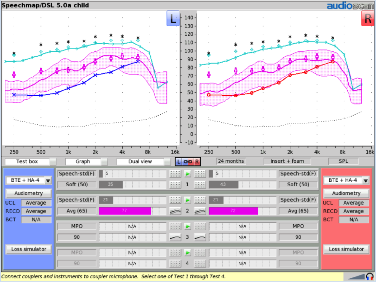
Figure 1. Audibility-based hearing aid fitting using DSL 5.0a for a 24-month-old child.
In Figure 2, note that the aided speech banana represented in pink for normal conversational speech energy has been placed within the listener's audible window for both ears. This was accomplished by adjusting gain until the aided LTASS (Long Term Average Speech Spectrum), which is the thick pink line, reached the target. In addition, compression was adjusted to keep the banana width within the bottom half of the indicated audibility range.
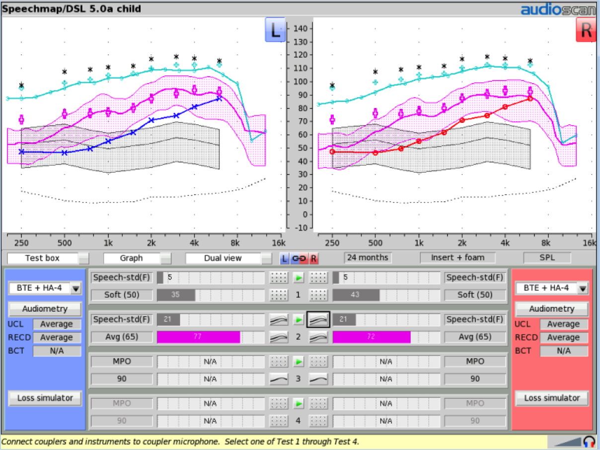
Figure 2. Hearing aid programming results.
Unaided normal conversational speech is represented by the gray-shaded area. If you compare this to the aided conversational speech range represented by the pink shaded area, you see that the hearing aid fitting has restored a significant amount of speech audibility. This is revealed not only by the position of the aided speech banana, but also by the improvement in aided Speech Intelligibility Index (SII) score compared to the unaided SII score for both the left and the right ear, which is listed below the curves. For average speech (65 dB), the SII for the right ear unaided is 21, and for the right ear aided is 72; for the left ear unaided is 21, and aided is 77.
Step One: Evaluate EHA65-SPL Without the FM Receiver Attached
The first step in the supplement A procedure is to get the aided speech banana recorded again for use as a reference prior to completing the FM test step. The coding for this test is EHA 65 SPL, which means an electroacoustic test with the hearing aid only, with 65 dB SPL speech input.
The steps involved are as follows: 1.) Place the already programmed hearing aids in the test box, (Note: if you have a previously measured RECD it should be re-entered and used to individualize the Speechmap configuration); and, 2.) Record the test results for this input level without any FM hardware attached or involved.
Figure 3 shows the physical set up needed in the Verifit2 test chamber.
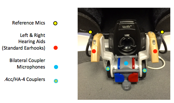
Figure 3. Picture of test box set up for step one.
The two hearing aids are coupled to a bilateral coupler microphone, and attached in this case using the HA-4 coupler. The HA-4 coupler has BTE tubing that is attached at one end to the earhook of the hearing aids, and at the other end to the TRIC (Thin-tube, Receiver in Canal)adapter which snaps on to the 0.4 cc wideband coupler. Then, the two reference microphones of the test box are placed near the front microphone of each hearing aid. The hearing aids are facing the front test box speaker that will create the speech signal used to execute the test.
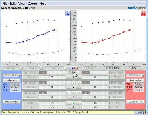
Video 1.
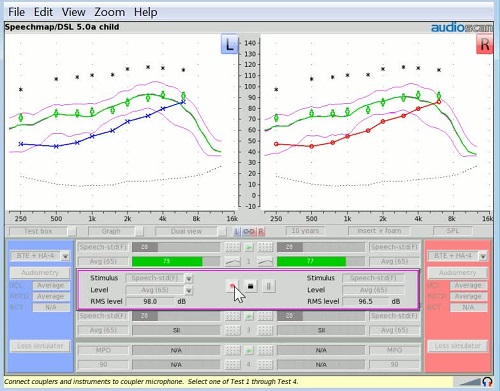
Video 1 shows how the test is completed. The Verifit 2 Speechmap screen displays the left and right SPL audiograms (blue and red lines) and the estimated UCL’s (black asterisks). Combined, these define the patient’s listening range in SPL for each ear. The selected rule is DSL 5.0a for a child 10 years of age. Because the instruments being tested are BTE’s coupled to the test box microphones with the HA-4 coupler assembly, the “BTE+HA-4” option in the Instrument menu is selected for each ear. The ‘Left/Right’ link button has been selected so that when the test is activated, an aided result for each ear will be measured simultaneously.
Selecting the Play button for Test 1 begins that test. The stimulus used in this example is Speech-std(F), which is calibrated speech, and the selected level is 65 dB SPL, (average conversational speech). By selecting the record (red) button, the long term average aided response for both ears is collected. Since these hearing aids have already been programmed to meet this patient's hearing loss needs, one would expect that the aided LTASS (the thick green lines) would approximate the target levels (the green plus signs). As can be seen in the video, that is indeed the case.
Step Two: Evaluate EHA/FM65-SPL with FM Receiver Attached, and Transmitter On But Muted
In step two of the procedure recommended in Supplement A, a second test of the hearing aids’ aided responses is obtained, but now with the aids in the FM+HA mode. The test code here is EHA/FM65 SPL, which means an electroacoustic test of the hearing aid in the FM+HA mode using a 65 dB speech input stimulus. To complete this step, attach the FM receivers (if they are external, or boot-type receivers) to each of the hearing aids in the test box. Next, turn the FM transmitter on, and place it to the side of the test box. Finally, set the transmitter in its “Mute” mode.
Figure 4 shows this test box set up. The only thing different from the first test setup is that the FM receivers have been connected to each of the hearing instruments.
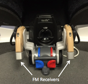
Figure 4. Test box set up for step two.
The transmitter set up can be seen in Figure 5.
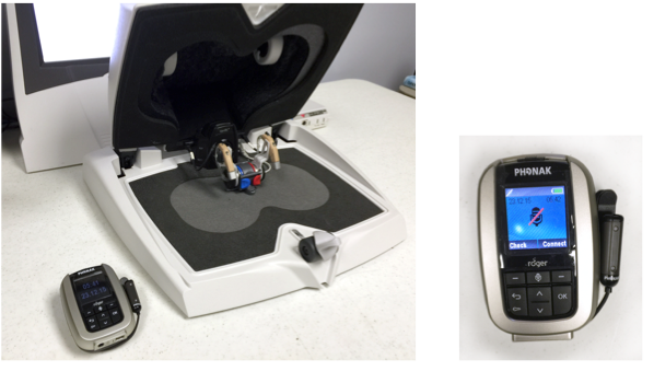
Figure 5. Transmitter set up.
In Figure 5, the FM transmitter is turned on and set off to the side. The close-up picture of the transmitter, indicates that it has been placed in Mute mode.
Video 2.
Video 2 demonstrates how test 2 is executed. Starting with the same Speechmap screen as shown at the end of Video 1, Test 2 is now selected. Using the same input stimulus type and level as selected for Test 1, a second set of aided results is now obtained with the hearing aids in the FM+HA mode, with the FM receiver boots attached, and with the FM connection engaged but with no signal coming from the FM system. The reason that the FM transmitter is set to mute is because the aided speech result being measured is still with the input signal reaching the hearing aid microphones. However, the electrical connection to those hearing aids that the FM system utilizes is in place. We simply don’t have an FM signal reaching those hearing aids just yet.
In the video, two new aided results (now in pink) are obtained. These results, when displayed on top of the Test 1 results, should look virtually identical. Through the hide/show icons available for each test, the shaded areas can be hidden so that just the aided LTASS lines remain. When displayed this way, the green and pink lines should match, as depicted in this video.
Step Three: Evaluate EFM/HA65-SPL With the FM Transmitter On and In the Box and the Coupler/HA Outside the Box
The third step in the Supplement A process is an electroacoustic evaluation of the FM system itself, and how it delivers speech to the hearing aids. The code for this test is EFM/HA65-SPL which means an electroacoustic test of the FM signal with the hearing aid in FM+HA mode using a 65 dB SPL speech input stimulus.
To prepare for this step, first unplug and remove the entire hearing aid/coupler assembly that is in the test box. The coupler cable easily unplugs from the right side of the test box speaker. Place this assembly off to the side of the test box. Then, unmute the FM transmitter and place just the microphone of the transmitter in the test box at the designated test location. Using an Audioscan coupler microphone extension cable, reconnect the coupler microphone (which is now outside of the test box) to the Verifit system. This allows you to measure the hearing aids’ outputs while the speech signal is sent to the FM transmitter microphone located in the test box.
Figure 6 shows the hearing aid coupler assembly outside of the test box with the coupler microphone extension cable reconnecting to the Verifit system.
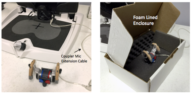
Figure 6. Coupler microphone set up.
In a reasonably quiet room, the coupler microphone/hearing aid assembly can simply be placed on the table off to the side of the test chamber. If the noise level of the testing room is a concern, this assembly can be placed inside a foam-lined enclosure to further isolate the environmental microphones from any input stimulus that might be coming from the room noise. Place the FM microphone in the test box at the crosshairs point, with the front transmitter microphone closest to the test box speaker and the reference microphones of the test box placed within 1-3mm of the front transmitter microphone opening (Figure 7).
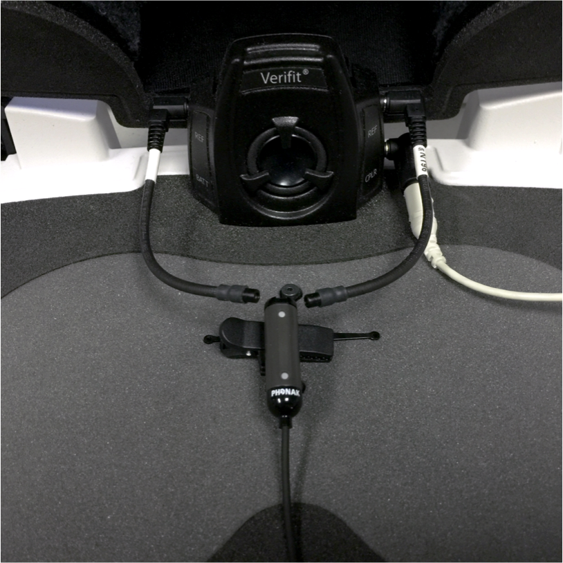
Figure 7. Transmitter microphone setup.
Figure 8 shows the entire set up with the unmuted FM transmitter sitting off to the side.
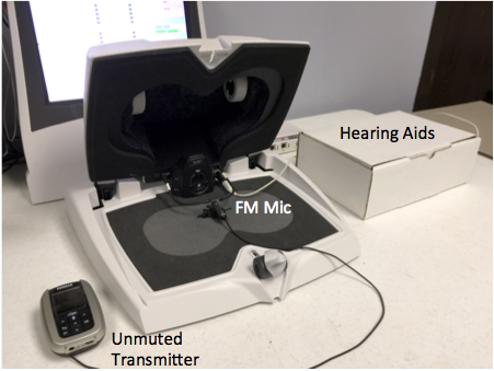
Figure 8. Completed setup.
The FM transmitter microphone is properly oriented inside the test box. The two hearing aids are still attached to the coupler measurement microphones with the extension cable connecting them to the Verifit system.
Video 3.
Video 3 is a recording of this third test procedure. Start Test 3 by hitting the play button. Using the same input signal type and signal level previously used, click the record button. This procedure measures the long term average of the speech passage as it is being presented to the FM microphone, transmitted to the hearing aids, and produced as output in the couplers.
Once Test 3 is completed, compare the LTASS of test 3 with the LTASS of test 2 to see if they are a close match, or close enough together to justify transparency. What is meant by a close match? The AAA guideline provides a calculation and a tolerance that can be used to determine the adequacy of the match. To perform this calculation, first determine the output result that was measured for Test 2 and Test 3 at 750 Hz, 1000 Hz and 2000 Hz. Record them on a worksheet as you see in Figure 9.
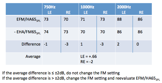
Figure 9. Results calculation worksheet.
There are two ways to find these output numbers. First, by placing the mouse cursor over either SPL-o-gram on the Verifit2 screen and left mouse clicking, a cross-hairs image will appear on that graph. You can move that cross point anywhere on the screen. In the upper left corner of the SPL-o-gram is a display of the frequency and intensity values identifying the selected cross point. Place the arrow cursor on the graphs at each of the two curves for 750, 1000, and 2000 Hz for each ear to display the level at each of those points. Figure 10 is an example with the cursor placed at 981 Hz for the left ear, and the level reading circled in red.
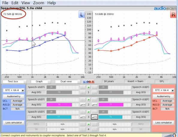
Figure 10. Obtaining output numbers via graph display using the cursor.
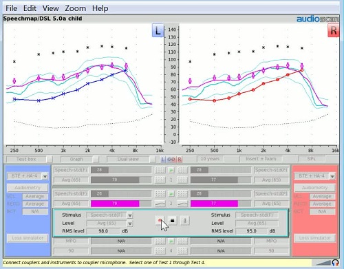
Alternatively, you can change the display from graph to table as shown in Figure 11.
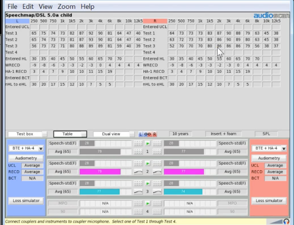
Figure 11. Table display.
The table displays the actual numbers for each of the targeted frequencies for each of the tests, for both ears. Simply transpose these numbers to the results calculation worksheet.
The results calculation worksheet in Figure 9 shows the numbers for Test 2 and Test 3 at 750, 1000, and 2000 Hz for both the left and right hearing instruments. Simply subtract the test 2 numbers from the test 3 numbers to get a difference value for each frequency. (For the left ear, the difference at 750 is -1, in this example.) Average the difference numbers for each frequency for each ear to obtain the number needed for the tolerance calculation:
Left ear average difference: (-1 + -1 + 2) ÷ 3 = +.66
Right ear average difference: (-3 + -3 + 0) ÷ 3 = -2
If the average difference is less than or equal to +2, there is no need to change any of the FM settings. If the average difference is greater than +2, change the FM settings and then re-evaluate the third test to see if the new result is now within the accepted tolerance.
It is often useful to supplement this procedure with your own listening checks using simultaneous inputs to both the FM and the hearing aid. Consider making adjustments to the offset if you feel that such an adjustment is needed or would provide value in overall FM system utility.
Behavioral Testing of FM System Advantage
In addition to the electroacoustic test guidelines recommended for verifying transparency of FM systems, Supplement A also includes recommendations for behavioral tests that can be useful in confirming an in-use FM advantage.
At its core, three sound field aided speech discrimination tests are to be conducted. The first is an aided speech discrimination test in quiet using a normal conversational speech input at 65 dB SPL (average conversational speech) with the subject wearing their hearing aids only. This would represent an ideal listening condition. Then, aided speech discrimination at a 0 dB signal-to-noise ratio using multi-talker babble at a normal conversational speech level is obtained, again with the hearing aid only. The third test is aided speech discrimination testing again at 0 dB signal-to-noise ratio, but with the FM transmitter now engaged in addition to the hearing aid environmental microphones. The score in the third test with the FM system activated, should be comparable to the discrimination in quiet score obtained in the first test.
If behavioral tests are conducted in a sound suite configuration that has only one sound field speaker in the test room, then the discrimination test will need to be conducted via live voice with the tester wearing the FM transmitter while in the control room. For the first two tests, the FM transmitter is off and both the signal and the competing noise signal are coming out of the same sound field speaker. They are controlled by the audiometer's attenuator to the delivered target SPL level for the listener's ear. For the third test, the tester wears the FM system that is now turned on. Since the FM microphone is in close proximity to the speaker's mouth, the signal level reaching this microphone is louder than the audiometer attenuated signal coming from the sound field speaker. This higher intensity FM signal now reaches the subject's ears though the FM receivers, and should provide the signal-to-noise improvement associated with the FM level setting utilized. With at least a +10 FM advantage, this FM enhanced in-noise discrimination score should equal the previously acquired in-quiet score.
For test suite systems that have 2 sound field speakers at either 90 degrees or 180 degrees relative orientation, it is possible to deliver the speech signal and the noise signal through separate speakers. This arrangement also facilitates the use of recorded word lists for all three tests. When the third test that incorporates the FM signal into the listener experiences is to be performed, the FM transmitter is now placed in the test suite at a position in front of the speech-only sound field speaker. It should be placed at a distance from the speaker that emulates the distance from the talker's mouth the FM microphone would occupy when worn. For example, a lavalier microphone would be placed a few inches further away from the speaker than a boom microphone.
Speech recognition with FM in noise should be significantly improved over performance in noise with the hearing aids alone. The goal is that speech recognition results from the FM in noise test should be commensurate with speech recognition performance in ideal listening conditions. The ideal listening condition is: FM microphone muted or off, with no competing noise.
On-Ear Verification of FM-Only
On-ear verification of FM only capabilities would be particularly useful if you are using an FM system or remote microphone system on a patient who has an open fitting where test box coupler measures are not possible, or for a patient who has normal hearing. (The protocol being described here is also included in the Supplement A documentation.)
As an example, an audiogram that has normal hearing in the low and mid frequencies, and a moderate hearing loss in the higher frequencies will be utilized. Such an audiogram would likely be addressed with an open fitting. Before executing the recommended test protocol, configure the Speechmap screen so that the test mode is “On-ear” rather than “Test Box” and the instrument selection is set to “FM”.
In this example, the single view mode (which displays the measure of one ear at a time) is being used (Figure 12).
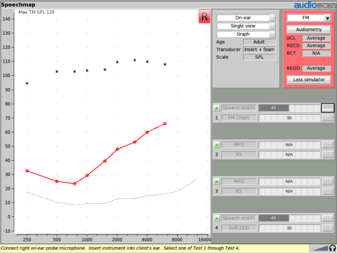
Figure 12. Speechmap screen set up to do on-ear testing using FM instrument.
This would be the default configuration when using a Verifit classic. However, with the Verifit2, the On-Ear FM protocol can be completed with both the right and left probe microphones measuring the on-ear results simultaneously. If the FM or remote microphone system being used is expected to produce results in both ears, this Verifit2 setup would be very useful.
To test an FM under this condition, place the probe microphone in the patient’s ear, and then place the hearing instrument/FM receiver device in that ear as well.
In this example, an FM receiver system which is paired with a Roger Pen is being utilized. This would be a remote microphone example, but the same procedure could be conducted with a more standard FM transmitter. The FM transmitter is now placed in the test box, with the coupler microphone assembly removed. The front microphone of the transmitter is positioned at the crosshairs, and the reference microphones placed within 1-3 mm of the front transmitter microphone (Figure 13).
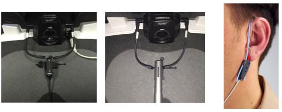
Figure 13. Test set up – FM transmitter in the test box and patient wearing probe mic and FM receiver.
With the instrument selection set to FM, the first test that will be conducted will be an RESR or real-ear saturation response test with the receiver system set at the maximum volume control setting (if a volume control setting is available). Note that because the instrument selection is set at FM, the input signal is going to be presented to the transmitter microphone in the test box even though the measurement is being made with the probe microphone in the patient's ear. Also note that it is important to ensure that the maximum output of the system will not exceed the patient’s predicted (or measured) uncomfortable loudness levels. As such, the ‘Max TM SPL’ feature can be adjusted in the setup screen or in the MPO test signal window to turn off the test signal should the selected SPL value be exceeded at the eardrum.
Video 4.
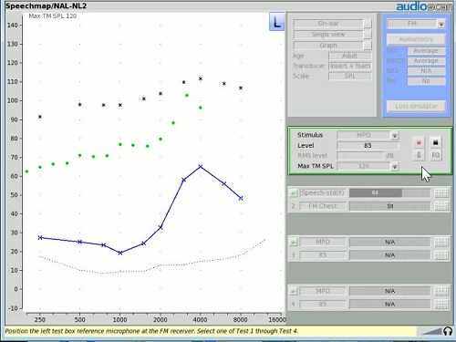
Video 4 is a demonstration of this initial RESR response with MPO selected as the test condition for Test 1. Once the record button is selected, an on-ear output measurement (green line) is obtained with the signal driving the transmitter in the text box.
Under these test conditions, the SPL reaching the probe tip during this test is affected by two important factors. First, because this is an open fitting, there is a large vent effect that is bleeding a fair amount of SPL out of the ear canal in the low and mid frequencies before this SPL can reach the probe tip. Second, this is a loud input stimulus, in this case 85 dB SPL pure tone beeps, being presented to an FM transmitter that has an FM offset feature with a 70 dB kneepoint and a 10:1 compression ratio. As a result, the output being measured will likely be noticeably below the UCL indicators on the SPL audiogram screen for a broad portion of this saturation response measurement. The Supplement A guideline recommends that MPO testing be done with hearing aid only because when such a test is done in the fashion demonstrated here, these sorts of effects will be evident.
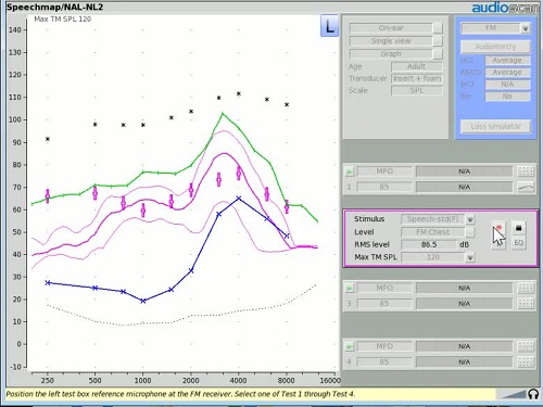
Once the initial RESR has been captured, the hearing aid is returned to its use gain setting if necessary and a real-ear aided response (REAR) is obtained in Test 2. Because FM is the selected instrument in the instrument menu, two new input level options will now appear when starting the REAR test: “FM Chest”, which produces an 84 dB SPL speech passage; and “FM Boom”, which produces a 93 dB SPL speech passage. Since both of these two signals exceeds the FM offset kneepoint of 70, the resulting real-ear aided response will be a reflection of the REAR that reaches the listener's ear through the transmitter worn or held in a ‘chest’ or ‘boom’ location.
In the following video (Video 5), Test 2 is activated and the FM Chest input level is selected prior to clicking on the record button to secure a long-term averaged result. The provider would likely adjust the settings of the hearing instrument based on this test result to get the aided LTASS approximating the target values displayed. In this example, an NAL-NL2 target has been selected.
Video 5.
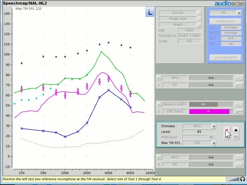
The third and final measurement recommended in the Supplement is a repeat of the RESR done in Test 1, but now with the hearing aid remaining at its use gain setting. It is demonstrated in Video 6.
Video 6.
In Video 6, the play button of Test 3 is selected, and the test is set up to complete an MPO sweep. A second saturation response is obtained reflecting the output of the hearing aid at the use gain setting.
At the end of this entire procedure, a summary screen that looks like the one in Figure 14 is obtained.
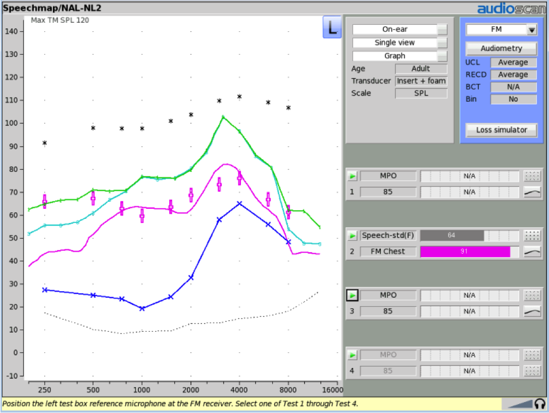
Figure 14. Final results screen.
This procedure verifies that the output from the FM transmitter in an FM only condition will not produce an output that exceeds the patient's uncomfortable levels even if the volume control is adjusted. And, this procedure verifies that the FM-only transmitted signal produces acceptable audibility, in this case, target audibility, in the patient's ear.
Summary
The AAA 2008 guidelines, including the 2011 Supplements represent the most current thinking regarding FM system verification of modern (compression) systems. Supplement A of this guideline outlines specific clinical protocols for testing and verification of ear-level FM systems, including an electroacoustic protocol for verifying transparency. This course has described and demonstrated the three steps involved in the successful implementation of this protocol. In addition, Supplement A includes a behavioral protocol for verifying FM advantage, which was covered in this course for a variety of clinical test booth configurations. Supplement A also includes an on-ear protocol for verifying FM-only input signal audibility and target match, which is particularly suitable for open fittings (where test-box measures are not possible) or when using remote mic assistance in the presence of normal hearing. This procedure was also described and demonstrated.
Speech, and ideally calibrated speech, is the preferred stimulus to use when evaluating FM systems. Much, if not all of the verification process described in this course can be used to verify any remote microphone technology, even if it's not a school FM system.
Readers who have any questions or would like further clarification on any of the information presented in this course are invited to contact Audioscan either via phone (Canada, 519.268.3313; USA, 800.265.2093) or email ([email protected]).
References
American Academy of Audiology. (2008). Clinical practice guidelines: Remote microphone hearing assistance technologies for children and youth from birth to 21 years. Available from author at www.audiology.org
American Academy of Audiology. (2011). Clinical practice guidelines: Remote microphone hearing assistance technologies for children and youth from birth to 21 years (includes Supplement A). Retrieved from: https://audiology-web.s3.amazonaws.com/migrated/HAT_Guidelines_Supplement_A.pdf_53996ef7758497.54419000.pdf
American Speech-Language-Hearing Association. (1994). Guidelines for fitting and monitoring FM systems. ASHA, 36(Suppl.),1-9.
American Speech-Language-Hearing Association. (2002). Guidelines For fitting and monitoring FM systems. ASHA Desk Reference.
Lewis, D.E. & Eiten, L.E. (2004a). Assessment of advanced hearing instrument and FM technology. In D.A. Fabry and C. DeConde Johnson (Eds.), ACCESS: Achieving Clear Communication Employing Sound Solutions-2003. Proceedings of the First International FM Conference. (pp. 167-174). Available from Phonak AG.
Platz, R. (2003). SNR Advantage, FM Advantage and FM Fitting. Chapter 14 in ACCESS 2003 Phonak Proceedings https://www.phonakpro.com/.../2003proceedings_chapter14.pdf2008 Phonak FM Offset Protocol from Phonak.com
Scollie, S.D. (2003). Hearing aid test signals: what’s new and what’s good for kids? The Hearing Journal, 56(9), 10–15.
Scollie, S.D. and Seewald, R.C. (2002). Evaluation of electroacoustic test signals I: comparison with amplified speech. Ear and Hearing, 23(5), 477–487.
Stelmachowicz, P.G., Kopun, J., Mace, A.L. and Lewis, D.E. (1996). Measures of hearing aid gain for real speech. Ear and Hearing, 17(6), 520–527.
Citation
Smriga, D. (2016, May). Clinical verification of ear level FM systems: Classroom & personal use applications. AudiologyOnline, Article 17322. Retrieved from www.audiologyonline.com