
Learning Outcomes
After this course, participants will be able to:
- Describe the electrode montages used for 1 and 2 channel ABR.
- Identify the difference between the infant and adult ABR response.
- Describe how increasing rate and intensity independently affects the ABR response.
Introduction
Thank you for joining me during this foundational course. We will mainly discuss the auditory brainstem response (ABR) test and cover basics of evoked potentials such as set up, equipment, and supplies.
Evoked Potentials
Evoked potentials are electrical signals that are generated by the nervous system in response to a stimulus and are event-related (i.e., evoked by the onset of stimulus). With evoked potentials, it could be a number of stimuli (e.g., visual, auditory, sensory stimuli). The selection of presentation stimuli is dependent on what type of evoked potential you are performing. Evoked potentials are useful in diagnosing a variety of neurological disorders.
Auditory evoked potentials (AEP). Including AEPs, there are numerous terms when referring to this evoked potential, most commonly used are: auditory brainstem response (ABR) and brainstem auditory evoked response (BAER). As audiologists, we focus mainly on auditory evoked potentials as a diagnostic tool to determine the integrity of the auditory system and make inferences about hearing. Remember performing AEPs is not a hearing test but it is a tool to predict hearing. Also, with auditory evoked potentials an acoustic stimulus generates a response measured using skin electrodes on the surface of the skin. The stimulus that is being generated is minimal; thus we have to use gain and amplify to measure the response. It also objectively tests the integrity of the hearing system from the level of the cochlea to the brainstem.
Within auditory evoked potentials, there are different types of tests you can do. In this course, we'll be focusing on the ABR. Within an ABR you are looking at the beginning of the response. Then with middle latency or late latency, you would be looking at a later response in time. As we discuss auditory evoked potentials, latency or time is a crucial component. Specific waveforms appear within a window of time, and that's critical when considering which test to perform. Examining each waveform and their latencies and measuring them against each other (right vs. left ear) is the focus of auditory evoked potentials.
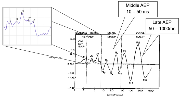
Figure 1. Overview of AEP in the time domain.
Recording evoked potentials. When we are recording evoked potentials, remember it's a far-field recording, and the electrodes are placed on the scalp. Electrodes are assigned either active (+), reference (-) or ground. You are recording from a pair of electrodes, you are recording from Cz to A1. You are also recording from a non-inverting, and an inverting electrode. Again, the non-inverting is the active electrode, and the inverting is the reference electrode. You can amplify the difference between the signals. What's critical is proper care of the electrodes. The impedance is significant because that's the medium for collecting the evoked potential data.
Recording EP data. When you are recording evoked potential data you use what's called common mode rejection. The voltage is different between the active and reference electrodes. The voltage related to noise is similar at both electrodes, and the response voltage has the most significant difference between them. The response of the reference electrode is added to the response of the active (i.e., non-inverting) electrode. The components which are common to both electrodes are canceled, so the biological or environmental noise is canceled out. Now because of this, inter-electrode impedance is the most important. Common mode rejection does not work well if inter-electrode impedance varies.
Preparation
Testing Environment
When we are prepping for any evoked potential, a critical element we need to look at is the testing environment. Frequently, issues are related to noise with an evoked potential. Here are some tips to help you cut back on the amount of noise:
- The preamp should not be near the isolation transformer, monitor, etc.
- Turn off unnecessary computer monitors.
- Do not have the preamp in front of the monitor.
- If possible use a designated outlet.
- If the patient is in a chair that plugs in – unplug it.
- Assure wall outlet is grounded.
- Do not use cellular phones during testing.
- Turn off fluorescent light(s).
- Do not have the dimmer switch set in the middle position.
The Chartr EP 200 preamp connects to the Chartr EP 200 Box by a six-foot cable to allow ample distance between the patient and computer. The electrodes, transducers and VEMP monitor plugs directly into the preamp.
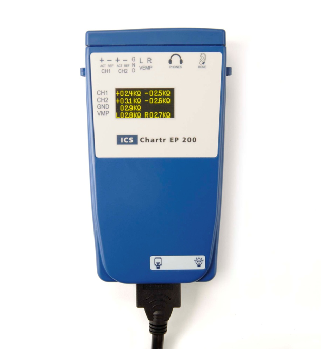
Figure 2. Chartr EP 200 preamp.
Electrode Placement
Figure 3 shows examples of electrode placements. True Cz, which is the top middle of the head, allows for a more substantial amplitude response. If you choose to use a high forehead, which many people do, it will create about a 15% reduction in amplitude. A1 is the left ear, A2 is the right ear, and ground placement on your forehead.
Figure 3. Electrode placement.
Types of electrodes. There are non-disposable and disposable electrodes that you can choose from (Figure 4): cup electrodes that are used with paste (left) and pre-wired electrodes (center). Some clinics decide to use the pre-wired electrodes because they are one-time use only, which is better for infection control issues if your hospital has strict protocols. They are also a bit expensive. The common snap electrodes (right) are a popular option as well.
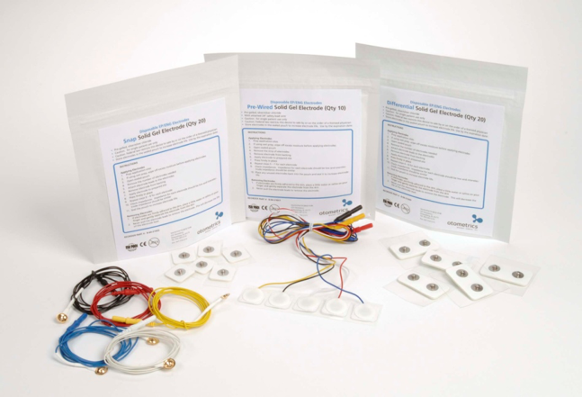
Figure 4. Different types of electrodes.
Skin prep. In Figure 5, there are examples of skin prep products to use. You want to prep the skin by using NuPrep (Left), or any other type of slightly abrasive cleanser where you are putting the electrodes down. There are also different types of pads. These are electrode prep pads (Right). They look like alcohol pads, but they have pumice in them which will help clean the skin when you put electrodes on.

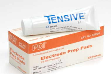
Figure 5. Types of skin prep products.
Application of Electrodes
When applying any type of electrodes, including non-disposable and disposable, use the following guidelines:
- Tape the electrodes together (making a sleeve with the tape) or you can braid them together, that will help cut down on the noise.
- Do not mix electrode types.
- Do not want to mix the metals that are used on electrodes (i.e., silver, silver chloride, gold).
- Do not place the ground electrode near the heart because a large EKG can generate noise.
- Clinicians might use alternative placements for the ground electrode such as the sternum or the collarbone.
- If you are doing a bone conduction ABR, place electrodes on the front of the earlobes instead of the back.
- Explain to the patient the process of placing the electrodes.
- Gently clean the electrode site (do not abrade skin)
- Explain to the patient that you are going to clean their skin to make sure that we get all the dead skin cells off.
- Do not mix alcohol with NuPrep because this causes a stinging sensation.
- If you use Cz, an alcohol pad will help dissolve any hair products and will help reduce impedance.
- Electrodes on the earlobes or the mastoids should be symmetrical.
- All the electrode leads should run towards the top of the patient's head.
- As a best practice, do not turn the equipment on or off with the patient connected.
Non-disposable electrodes. Electrodes should be cleaned after each use. You can use a small toothbrush and warm water to remove any paste. Every site has their cleaning policy; some product companies might recommend an autoclave. Electrodes will not last forever; thus maintenance is essential. Bad electrodes will result in high impedance, and the waveform will be a noisy recording. You can get a low impedance with a lousy electrode, and suddenly you see excessive noise. Be aware and always have some backup electrodes available. A wet prep method works best instead of a dry prep. You can scrub the skin, but the wet prep works quite a bit better with the gel on the electrode. Then, prepare the electrodes by adding a small amount of paste by scooping the cup electrode in. Apply the electrodes firmly. You can use a piece of the cotton ball on top of the electrode, and then secure with a piece of first aid tape. After application, wait a moment for the electrodes to settle. Typically I take a moment to see what are the impedances because sometimes they start high and reduce. Also, be aware of silver chloride. Regularly check to see if they need to be re-chlorinated. To re-chloride the electrodes, place the cup of the electrodes into a small amount of chlorine bleach and soak for approximately 20 minutes. Do not let the wires touch the bleach, just the cup portion.
Disposable electrodes. With disposable electrodes, typically the dry prep works best. On the back of your snap electrode, you can put a drop of water or saline, and it will make the gel stickier. Some disposable electrodes can be cut down in size.
You want to keep your electrodes together. Here's just a quick step-by-step of how you make a sleeve for the electrodes. Some people like to braid them. Other people like sleeves because if one of the electrodes goes bad, you can quickly add on another. Again, the purpose of that is to cut as much noise down as possible.
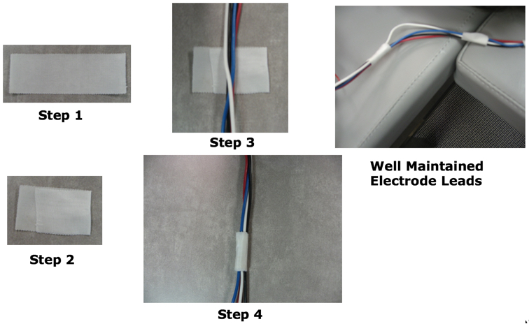
Figure 6. Steps to keep electrodes together.
Patient Comfort
Patient comfort is important. Send your patient to the restroom before testing, you want them to be as comfortable as possible. You want the patient to feel secure and comfortable in the chair or table. Consider a table or chair with arms. You want to have blankets and pillows to assist with comfort, and putting a pillow under the knees can help support the lower back of an adult patient. Finally, be sure and explain the test procedure before placing the earphones on.
Application of Earphones and Cable Position
Electrodes go up, and we want the transducer cords to go down. Instruct the patient before placing your insert your tips in. If they have a hearing loss already, you do not want to impede their hearing even more before giving instructions. Always choose the largest size of ear tip to reduce the risk of stimulus leakage. That can cause a reduction in dB SPL in the ear canal which can create poor results or low amplitude. Compress the foam tip, insert entirely and hold in place until it's expanded. Separate the electrode leads from the transducer cable using the patient's body and do not clip the stimulus transducer box to the patient. For infants, beige tips can be trimmed down. Also, you can use infant tips.
Patient Setup with Chair
You can see we have the electrodes in Figure 7 taped together. He likely has electrodes on his mastoids, but we are not able to see them. Then we have the transducers with the tubing going in the ear, and a wire for the transducers going downward.
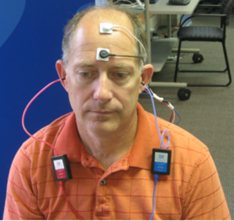
Figure 7. Patient setup seated in a chair.

Figure 8. Side and back view of patient setup in a chair.
Patient Setup with Table
When laying a patient down on a table, you can have the preamp next to the patient (Figure 9). You do not want the preamp sitting on them near their heart, or laying on their chest. One thing I'm going to point out in this picture is patient does not look very comfortable. I am concerned about the myogenic activity that could potentially be occurring because their neck looks uncomfortable. You could put a pillow underneath to make that more comfortable.
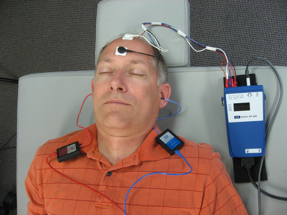
Figure 9. Patient setup with a table.
Figure 10 shows a diagram of where to place the electrodes. When you have the electrodes on it will show you the impedance on the preamp box. However, that does not last the entire test.
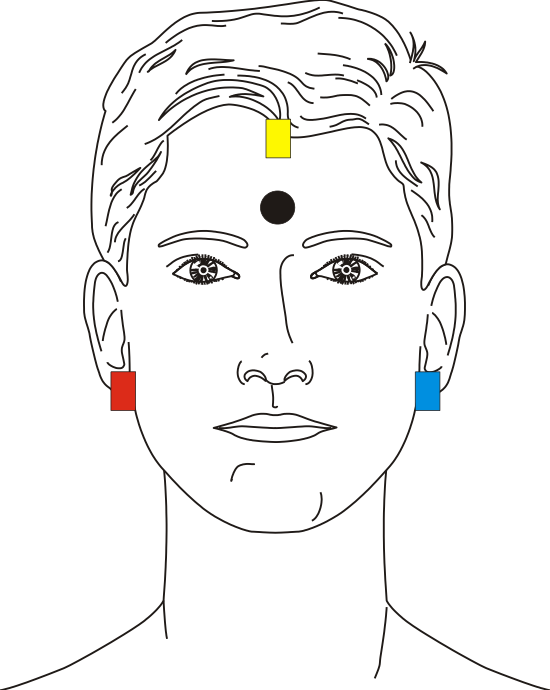
Figure 10. Proper electrode placement.
Electrode Montages
One channel recording with electrode switching on. Figure 11 shows a diagram of a one channel recording with electrode switching on. Electrode switching occurs when you use a one channel recording. Your ground is one ear, reference is the other ear and active is on top. On a typical one channel recording, you would need to physically switch the electrodes in the preamp box. This way you could test the right ear, and then the left ear. When you have electrode switching on within a one channel recording, the equipment does that automatically for you. With electrode switching on, you do not switch it over yourself.
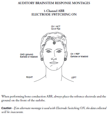
Figure 11. One channel recording with electrode switching on.
One channel recording with electrode switching off. You have to manually switch the electrodes on the preamp. You would unplug the electrodes and flip them around.
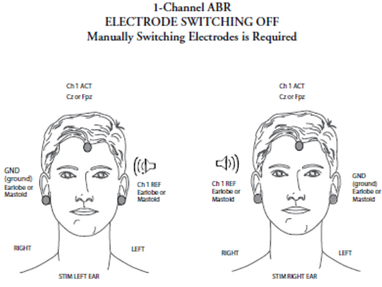
Figure 12. One channel recording with electrode switching on.
Two channel recording. With a two-channel recording, you do not have to worry about that at all. The ground is always your low forehead, Cz or your high forehead is jumpered, and it's your active channel. Then your reference channel one is your left ear, and channel two is your right ear.
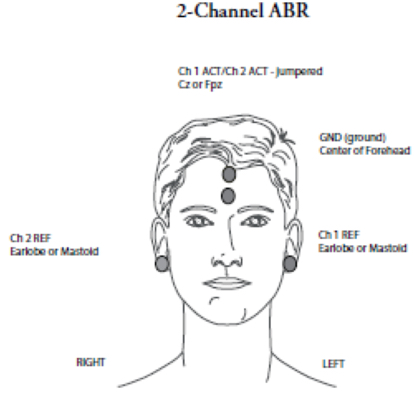
Figure 13. Two channel recording.
Setting up a New Patient Record
Birthdate and gender. When you set up a new patient record, you must enter the birthday and gender to obtain normative data. You do not have to enter a name but can use a medical record number instead. You want to be able to identify the patient, but if that's a concern you could use an identifier. One other thing to point out if you are testing a baby, you want to enter in their weeks at birth. The software will take the birthdate into account, This is an important feature for any pre-term babies when you are performing ABRs.
Impedance
Within the software click or press F7 to check your impedance. The VENT monitor will be visible if you are doing a VENT, and the monitor is plugged in. The goal is to have low electrode readings of <5KOhms each with no more than <2KOhms difference between electrodes. Inter-electrode impedance is the most important (common mode rejection does not work well if inter-electrode impedance varies). ChartrEP 200 reads up to 80 kOhms.
Selecting a Protocol
On the left-hand side of your screen within the software, there are three tabs: review, new test, and settings. If you click on new test, it will show you all the different protocols that are available. When you purchase the base equipment in the Chartr EP, this automatically comes with ABR, ECOG, ALR, and AMLR. Some optional choices for testing, which is an additional fee to get the software added on is ASSR, VEMP, and P300.
Listening Check
You want to do a listening check routinely. If the softest level anyone with normal hearing can hear the stimulus is 20 dB, then there's a 20 dB correction factor. This is where you figure out within your equipment what are your correction factors for your clinic. Subtract the correction factor from the response obtained on the dial. If the patient's threshold is 60, then 60 minus 20 is 40, and 40 is their true threshold. If you are concerned about where your levels are, have your system calibrated. You need an annual calibration, but if there's suddenly some large concern when you are performing a listening check then you want to give us a call.
Click Air Conduction ABR
When you are performing an ABR, you are testing from the cochlear nerve to the level of the inferior colliculus.
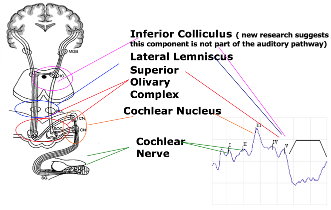
Figure 14. Anatomical and physiological principles of ABR.
Auditory Brainstem Response
With auditory brainstem responses, the markings that are used are the Roman numbers I through V. The main waves that we typically mark are I, III and V. Also on high-intensity waveforms, you can mark II and IV. Each peak represents a neural firing from a sum of activity arising from the areas within the brainstem and auditory nerve. Wave I and II are generated predominantly from the action potential on the ipsilateral side, Whereas, waves III through V are generated from the complex interaction of both the contralateral and the ipsilateral brainstem anatomy.
Determining Threshold and Presence of Response
To determine if a response or a threshold is present, both must be repeatable. The wave must look like a typical response, and follow the usual pattern when intensity is changed. Remember, when you decrease intensity; latency is longer. If you decrease in intensity; the amplitude is smaller. Absolute latencies should be comparative to normative data. The amplitude should be larger than the background noise by about three times. A threshold is considered the lowest intensity where a response is present and repeatable. No response is obtained at an intensity below where a threshold is determined. An absent response must be low in amplitude eliminating a chance that a response is buried in noise.
Ipsilateral vs. Contralateral Waveforms
When performing a two-channel ABR, you are looking at both the ipsilateral and the contralateral waveform. What does this look like comparatively? Note that in a contralateral waveform, there is no wave I and there is an enhanced wave V. If you are not positive, look at your contralateral waveform. In general, there will not be a wave I and your wave V will look better.
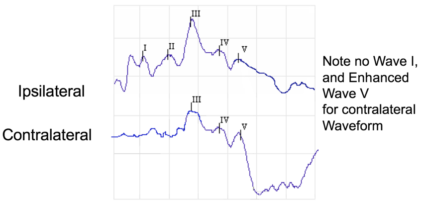
Figure 15. Ipsilateral vs. contralateral waveforms.
ABR Test Screen
You can split your screen to view the left vs. right ear during testing. All of your responses are on this left side under three different tabs: settings, new test, and review.
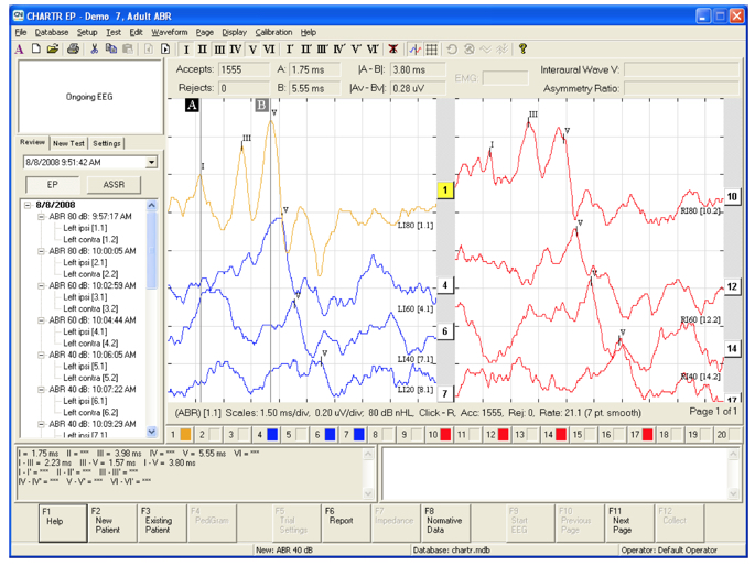
Figure 16. Screenshot of ABR screen during testing.
Purpose
The purpose of the ABR is to perform a threshold search. You can achieve that with either click or tone burst stimuli and at various intensities. An ABR can be used for babies or even for persons who might be developmentally delayed, and cannot respond in any other way. Also, you can perform an ABR for a neurologic assessment. This can compare peak latencies in a rate study, when searching for an acoustic neuroma, or any retrocochlear pathology.
What Should You Expect to Know After the Diagnostic Assessment?
With a threshold search, you are going to expect to know the type of hearing loss (e.g., sensorineural, conductive, mixed and auditory neuropathy). You can also determine the degree of hearing loss. You can even estimate the configuration of the hearing loss if you are using tone burst and clicks.
Click Air Conduction ABR
The click air conduction ABR is always the starting point. Using click air conduction ABR only, one cannot infer hearing loss configuration, or have adequate information for a hearing aid fitting because you are not looking at all frequencies. You are looking at a specific grouping of frequencies when you are performing click ABRs. It can miss both a high-frequency loss and a low-frequency loss.
Electrode montage. Your electrode montage for click air conduction ABR is non-inverting Cz or high forehead. Sometimes if the infant has a large soft spot, it's difficult to get a low impedance. Inverting A1 and A2, use the earlobe instead of the mastoid. If bone conduction is needed, you'll have fewer placement difficulties with the oscillator. You could also do an inverting Cz or the nape of the neck. Using a Cz instead of A1 and A2 could potentially help increase your amplitude of wave V, but you will decrease your detection of wave I. The ground is usually the center of the forehead.
Tips. You may need to open up your epoch window especially if the patient is an infant, or has neurological issues. Be aware of your window within the software, and if you need to open it up or make it larger, you certainly can. You always want to perform a biologic calibration routinely to determine if correction factors are required. Insert earphones are easier to use with infants than actual headphones. The only time I use headphones with infants is if they have an atretic ear. Software makes a 0.8-millisecond latency correction for insert earphones. Again, within the software, you can indicate which you are using.
Threshold search ABR for unsedated patients.
- Start at a moderate level - 60 dB nHL
- If wave V is present, decrease to 30 dB nHL
- If present, decrease to 20 dB nHL. This is within normal limits.
- If not present at 30 dB, bracket at 40 or 50 dB depending on the latency of response.
- If no response at 60 dB, increase to 80 dB
Latency Intensity Function
A sensorineural loss at higher intensities is going to fall within the normal range. As you get to the threshold it is going to fall outside of the normal range. With a conductive hearing loss, everything is going to be delayed regardless of intensity.
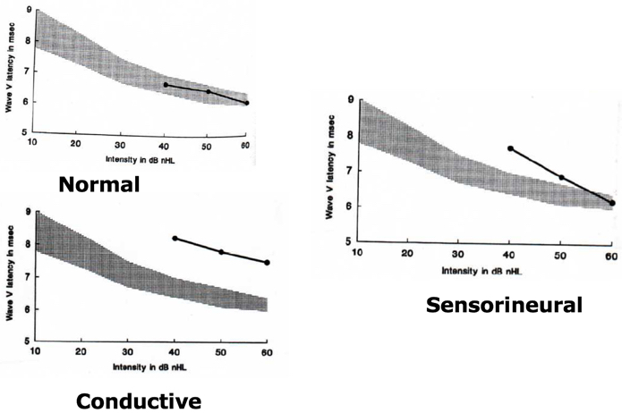
Figure 17. Latency intensity function.
Normative Data
Normative data includes a mean and standard deviation. There are norms within the software, and these results are determined within or outside of normal limits based on data collected by Dr. Michael Gorga from Boys Town. Age-specific normative data is included within the software.
Comparison Between Infant and Adult ABRs
With infants, the latencies are longer, whereas, adult's latencies are shorter. For a neurological assessment, what should you expect to know after the diagnostic assessment? You should be able to answer if the neural transmission of auditory stimuli intact.
Click Air Conduction ABR
This is done using air conduction ABR at a high intensity (i.e., 75, 80 and 90 dB nHL with adults) to evaluate the waveform morphology. In regards to waveform morphology, infants may have a larger wave I than a wave V and wave I to V interpeak latency.
Interaural differences. Comparison of interaural wave V of the absolute latencies can provide data sensitive to the retrocochlear pathology. Interaural wave V latencies should differ no more than by 0.2 to 0.4 milliseconds. Be careful to account for asymmetries in behavioral thresholds. The side with the later latency is the side that you are concerned about.
Interwave latency intervals. Waves I-III and III-V are 2.0 milliseconds approximately. Waves I-V are 4.0 milliseconds approximately. How do you figure out within the software the interaural time delay of wave V? You will need to highlight your wave V, hit control, and click on the second waveform that you want to compare. The waveforms that you are going to compare have to be of the same intensity.
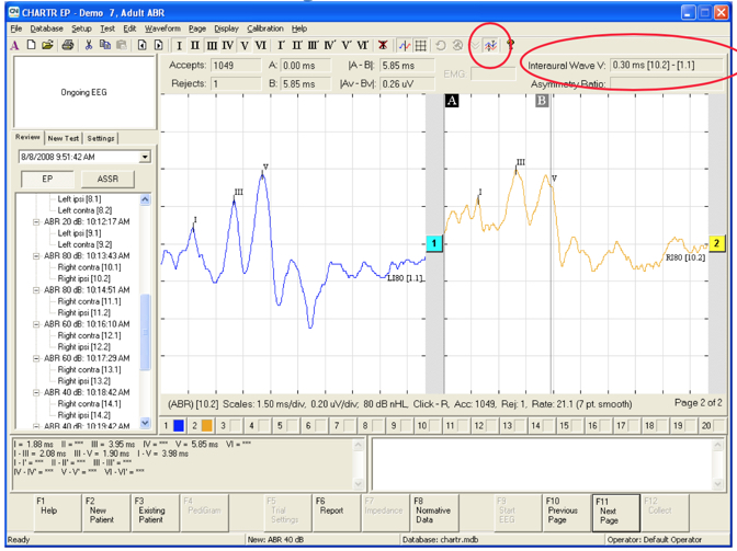
Figure 18. Screenshot of how to measure interwave latency intervals.
The interaural time delay of wave V. When considering changing click rates within a diagnostic ABR you will be presenting at a high intensity and a high click rate. This is because you want to tax the neurologic system.
Post-Auricular Muscle Artifact (PAM)
PAM occurs around 10 to 14 milliseconds and can be present in one run and not in the next. This artifact can effect latency and amplitude. Generally, PAM is caused by tension in the neck or jaw, not being centered, or lack of head or neck support. Figure 9 shows a gentleman laying down on the table, and he looked like he would probably have a lot of PAM because his shoulders and neck were scrunched up. You want to ensure that all of those things are taken care of. Put a pillow or folded towel behind the patient to make them more comfortable. Make sure the patient keeps their eyes closed, relax the jaw and no teeth clenching. If they wear a mouth guard, they should bring it to the appointment. You could try moving the electrodes off of the mastoids onto the earlobes because that could be causing some noise as well.
Figure 19 shows what PAM looks like within your recording. The ABR portion of your recording is going to be normal. It might affect the amplitude, but you are going to have these waveforms late within the tracing.
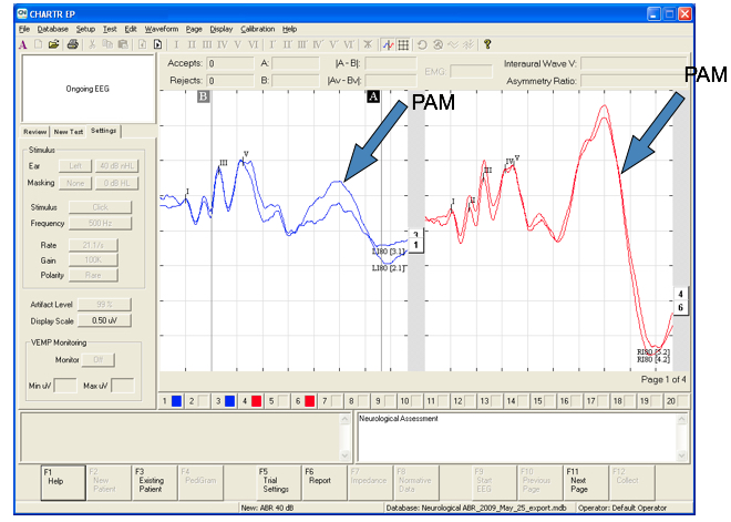
Figure 19. Post-Auricular Muscle Artifact (PAM).
Changes in Intensity, Rate, and Filters
How do changes in intensity, rate, and filters effect the ABR recording? There can be latency and morphology changes with a change in intensity. A decrease in intensity equates to an increase in latency and decrease in amplitude. The latency is much shorter, and your morphology of the wave is much cleaner at a high intensity.
Increased Rate Effect on Latency & Morphology
An increase in rate increases the latency and decreases the amplitude. Linda Hood (1988) states in her book Clinical Applications of the Auditory Brainstem Response to always use an odd number for the clicks per second so that the rate is not a multiple of the main power supply (i.e.,50 or 60 Hz). Otherwise, you could get a 60 Hz cycle running through the waveform. This looks at the increased rate effect on latency and morphology.
Effects of filters on the waveform morphology. Wider filters result in more fidelity. The narrower filters make the identification of the presence or absence of the response clear.
Test Protocol Screen
Within the software, Figure 20 shows the test protocol screen. The third tab is the settings tab, where you can change your trial settings. Within the settings tab, you can make quick changes (e.g., left ear to right ear, turning the masking on and off, stimulus).
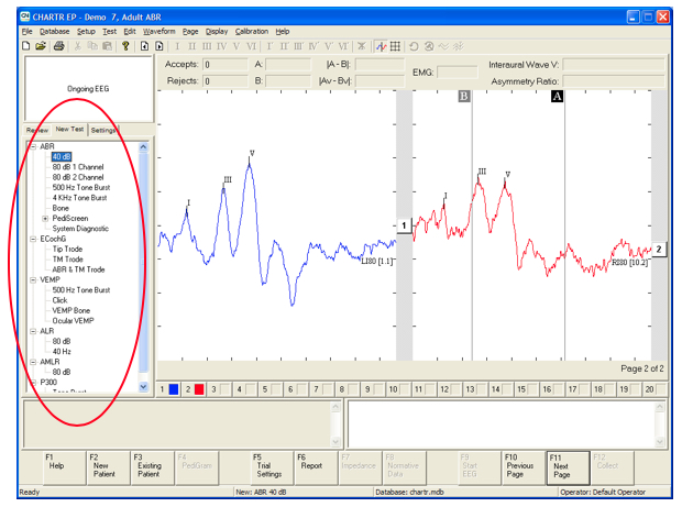
Figure 20. Test protocol screen.
Artifact Rejection and Averaging
The lower the number, the more rejection sweeps will occur. The default setting is 99%. Data larger than this value will be rejected, and data smaller than this value will be accepted. Averaging reduces the amount of noise and extracts the signal by 1 divided by the square root of N (number of sweeps) or 4 times as many sweeps averaged will reduce the noise by half.
With the data set at 99%:
- With gain set at 100k = 45.4uV peak to peak
- With gain set at 200k = 24.7uV peak to peak
Obtaining a clearer response. If you need a better response, you can increase your sweeps or increase the stimulus level. If wave I is obscured you can use a TMtrode, or gold foil Tiptrode like you would for ECOG. If wave V is obscured, you could record from the nape of the neck, or you could slow down the stimulus rate.
Click Bone Conduction ABR
To connect the bone transducer for the EP 200, there is a mini-jack that you can plug it into which is shown in Figure 21. The click bone conduction ABR provides a differential diagnosis of the type of hearing loss (e.g., sensorineural, conductive, mixed). Click bone conduction ABR provides the information you need to better counsel the infant's family to discuss what's the next step forward. This test is one way to diagnose infants with craniofacial anomaly and is the clearest way indicator of middle ear dysfunction. Additionally, it can be helpful when determining the plan for the child, such as hearing aids for a sensorineural loss or medical treatment for a conductive loss. Conventional tympanometry is not valid or reliable until six to seven months of age. You could use a 1000 Hz probe tone for tympanometry below the age of six months to get a better picture of what's going on. The one oscillator should be placed on the mastoid (using forehead can reduce output as much as 15dB ANSI S3.6 1996).
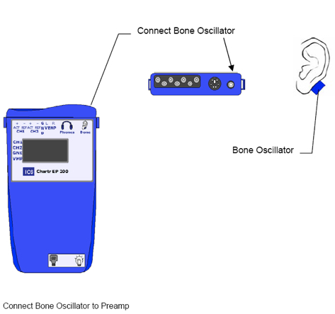
Figure 21. Connecting the Bone Transducer for EP 200.
Electrode Montage and Transducer Placements
You need to perform a listening check routinely. Always use alternating polarity and the earlobe instead of mastoid placement. Most bone oscillators headbands are too small for infants; thus hand-held placement can be used. Firmly hold the oscillator to the infant's mastoid with one finger. Or you could even use a huggie band similar to what you use for a bone conduction hearing aid to keep it in place. Push the oscillator on the mastoid until you could almost push the child’s head away from you. Transducer placement should be consistent to reduce variability. Never use two fingers to hold it as this can dampen the output.
Threshold search ABR.
- Start at a moderate level - 30 dB nHL.
- If you start too high, the infant may wake up.
- Do not exceed 50 dB nHL.
- You will overdrive the oscillator.
- Decrease in 10 dB steps.
- 20 dB nHL and below is within normal limits.
Toneburst ABR
Toneburst stimuli provide frequency specific information and can diagnose low and high-frequency hearing loss. ABR with tonebursts may take several attempts to replicate a wave. You always want to make sure you get repeatable waveforms. Toneburst stimuli are presented in notched noise, and they use a Blackman envelope (ramp), which is the most commonly used. For a 500 Hz toneburst, you need a 20-millisecond window because it is more difficult to obtain repeatable waveforms since there is less synchronous activity at that region of the cochlea. Remember that the latency of a 500 Hz toneburst is much longer than for your click stimuli, or for a high-frequency toneburst. If you are going to use alternating polarity, the response is a broad rounded peak. You are not going to get the sharp waveform. Using rarefaction polarity response is peakier. The response is about four to eight milliseconds longer than the click, and the cyclical stimulus ringing sometimes occurs which is not a response. There may not be a single peak, but rather a flatter area representing wave V.
Correction Factors
There are varying opinions on whether correction factors are needed for tonebursts. For 500 Hz toneburst, typically, it's a 20dB correction factor, 1000 Hz is 15dB, and 4000 Hz is 5dB. For 8000Hz, roll-off for insert earphones is around 5000 Hz; this may not be frequency specific. I would not recommend using 8000 Hz.
Neural Disorders
Infants in the NICU sometimes have a delayed neuromaturation, so carefully monitor NICU babies for any improvement within hearing. Patients with auditory neuropathy may have an abnormal ABR with present OAEs. Again, depending on a patient's situation or condition it's possible based on this delayed neuromaturation that things could normalize eventually.
Cochlear Microphonic
Your cochlear microphonic or the pre-neural response from the cochlea that follows the stimulus waveform suggests that the outer hair cells are intact. There is some neural response in the auditory pathway if the cochlear microphonic is present. Patients with auditory neuropathy have abnormal ABR with present OAEs.
References
Hood, L. J. (1998). Clinical applications of the auditory brainstem response (evoked potentials). Delmar Cengage Learning, Clifton Park.
Citation
Hill, K. (2018). Tinnitus toolbox. AudiologyOnline, Article 23607. Retrieved from https://www.audiologyonline.com