
Editor's note: This is an edited transcript of an Audioscan webinar on AudiologyOnline.
Learning Outcomes
- Participants will be able to describe key changes in the definition of the Real Ear to Coupler Difference due to a new ANSI standard.
- Participants will be able to explain how the RECD varies when measured with foamtips versus earmolds.
- Participants will be able to describe a new protocol for correcting the RECD that is applied in new Audioscan software systems.
Contributions
Dr. Susan Scollie: Thank you to Audioscan and AudiologyOnline for the opportunity to present this webinar.
Today’s webinar will cover key changes in the definition of the Real-Ear-to-Coupler-Difference (RECD) that came about due to a new ANSI standard. There is a large team of people who contributed to the research and information I will discuss today. Thank you to the team here at the University of Western Ontario, including Marlene Bagatto, Sheila Moodie, Paula Folkeard, Marianne Hawkins, Philip Narten, and Richard Seewald, some of whom are working on gathering further data in this area. The team from Audioscan, including John Pumford, Jim Jonkman, John Pietrobon, Chris Stokes-Rees and Bill Cole have worked very hard on gathering the background information, and putting it together into a usable software system.
There are several people in the pediatric audiology community who contributed to this work, including Eileen Rall and many colleagues at Children’s Hospital of Philadelphia; George Lindley, Pat Roush and other colleagues at University of North Carolina; and Ryan McCreery, Marc Brennan and their many colleagues at Boys Town National Research Hospital. Through their collaborations, interactions and sharing of cases, we have a better understanding of what we need to achieve in software systems that implement new standards for the RECD.
Brief Introduction to the New Standard
Verification of hearing aids is best practice, because we know that people of all ages vary in their ear canal acoustics (Bagatto et al., 2002; Saunders & Morgan, 2003). If we don't account for that variability, then some people's hearing aids could be too loud or too soft, and that might impact either their comfort and/or their benefit from the devices (Aarts & Caffee, 2005; Aazh & Moore, 2007; Kochkin, et al., 2010; McCreery, Bentler, & Roush, 2013). Hearing aid fittings should be individualized to protect against these large errors and ensure consistent audibility of speech (Mueller, 2014).
We can remove error caused by variation in ear canal acoustics by conducting real ear measurement. This is very well established and there are strong recommendations and clinical protocols for this practice (AAA, 2006, 2013; Bagatto et al., 2016). Real ear measurement generally takes two forms in daily clinical use: real ear verification and coupler-based verification. Real ear verification consists of placing a probe tube microphone in the ear canal with the person sitting in front of a loudspeaker. Test signals are presented from the loudspeaker to the hearing aid user. The probe tube microphone measures the levels of aided sound that are produced by the hearing aid, in the ear canal. When this first evolved, it was centered on real ear insertion gain (REIG) measurements. Current procedures recommend measuring the real-ear aided response (REAR), and plotting it on an SPLogram, which shows not only REAR but also thresholds of detection and discomfort (Mueller, 2015; Seewald et al., 2005). One advantage of this approach is that the hearing aid output is shown alongside thresholds and loudness discomfort levels, so that the hearing aid fitting can be viewed within a perceptual context.
With coupler-based verification, the hearing aid is placed on a coupler, and measurements of the hearing aid output are made. These measures are converted, to predict the sound pressure levels that the hearing aid would produce in the ear (Moodie, Seewald, & Sinclair, 1994). The Real-Ear to Coupler Difference (RECD) is used as part of this prediction. Coupler-based verification was developed for use with children and is considered part of recommended practices in pediatric hearing aid fitting (AAA, 2013). Coupler-based verification can also be helpful when fitting hearing aids to adults, especially for pre-fitting or troubleshooting when the adult patient is not available for real ear measurement.
ANSI Standards for Real Ear Measurement
ANSI S3.46-1997
The 1997 ANSI standard for real ear measurement (S3.46 1997) was the first to standardize real ear measurement terminology, such as Real Ear Aided Response (REAR) and many others we use today (see review by Pumford & Sinclair, 2001). The Real-Ear to Coupler Difference (RECD) was mentioned in this standard, however, it was in an appendix and not formally standardized.
ANSI S3.46-2013 and Standard RECD
The new ANSI standard for real ear measurement (S3.46-2013) is the first in North America to standardize the RECD. Of the various ways we measure the RECD in the clinic, only one is considered the standard form according to S3.46-2013. Like all RECD measurements, it is calculated as the difference between the response in the ear and the response in the coupler, for the same signal. However, in ANSI S3.46, the definition is a bit more specific: the coupler must be the HA1 coupler, the test signal must come from a high-impedance source transducer, and the same earpiece (either a foam tip or an earmold) must be used for both the ear measurement and the coupler measurement.
How does this new RECD standard apply to fitting a hearing aid with an earmold? If the earmold is used for the on-ear response and also for the coupler response, the earmold tubing effects will be cancelled out. Therefore, conceptually, the standard RECD accounts for the acoustic properties of the ear cavity itself and is not necessarily designed or intended to include earmold plumbing effects.
This is a new concept for many pediatric audiologists, because we are used to thinking about the RECD measurement as one that will account for the acoustical effects of a child’s earmolds, and we want to include that factor in the hearing aid verification process. So that is one issue that we wanted to consider in developing the new RECD protocols.
Figure 1 shows an earmold that is attached to the HA1 coupler with putty, which is how you would measure this standard RECD.
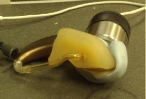
Figure 1. BTE with earmold attached to HA1 coupler using putty.
To measure this standard RECD, we have to have a way to attach the earmold to the HA1 coupler, and in this case we have used putty. Putty presents some practical challenges. For example, some earmold materials do not stick to putty. In addition, for infection control purposes, the earmold must be disinfected prior to each use of putty, or the putty must be changed from person to person (Adkins, 2014; Kemp & Bankaitis, 2000). These are just a few of the challenges we encountered in trying to measure the new standard RECD. Some solutions are presented later in this article.
ANSI S3.46-2013 is not wholly dedicated to RECD. Although this new definition of the RECD is getting a lot of attention, bear in mind that this standard is actually an update of a Real Ear measurement standard that was originally issued in 1997. There is a lot of good information in this standard on real ear measurement that is not the focus of today’s course, including the definitions of other real ear measures, information about test signals, information about room acoustics for making high-quality real ear measurements, and information about transforms including the RECD.
Evidence Review
Let’s discuss what prompted the RECD changes in this standard. Why would the RECD get standardized to be specific to the HA1 coupler and specific to just the ear canal acoustics? To answer that question, we’re going to go “under the hood” and look at five issues, including evidence on using the RECD, that were considered in the development of the standard.
Under the Hood #1 – How is RECD Used in Fittings?
RECD is used twice in many fittings (Bagatto et al., 2005). This may be happening behind the scenes in software systems, depending on the prescriptive formula you use. We first personalize the assessment data when we are building an SPLogram. We convert the audiogram in dB HL to dB SPL in the ear canal, using measures made from an individual’s ear canal whenever possible.
Then, we personalize the hearing aid fitting prediction by using the coupler-based verification curves to predict the hearing aid output in the ear canal. Again, we want to be as individualized and accurate as possible.
We incorporate the individual's ear canal acoustics and the earmold acoustics in one or both of these places, as appropriate. You can see these uses of the RECD in the diagram in Figure 2.
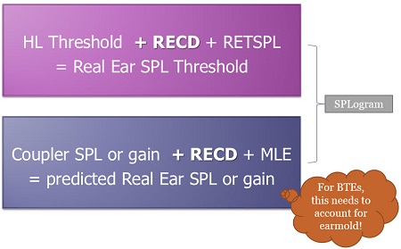
Figure 2. Diagram showing the two places in the process where the RECD may be used in hearing aid fitting (the top example is specific to insert phone audiograms).
The first use of the RECD is shown in the pink box at the top of Figure 2. Here, you see that the audiogram thresholds are added to the Real-Ear-to-Coupler Difference (RECD) along with the Reference Equivalent Threshold Sound Pressure Level (RETSPL), which is the calibrated level of sound that should be produced by your audiometer. The result is the Real Ear Sound Pressure Level (SPL) threshold shown on the SPLogram. That is one use of the RECD.
The blue box at the bottom of Figure 2 shows the second time that the RECD gets used. Here, the coupler SPL or gain is added to the RECD and the microphone location effect (MLE), and that gives us a prediction of real ear SPL or gain - depending on whether we measured SPL or gain in the coupler. (Note that some systems add a stored MLE, while other systems filter the MLE into the shape of the test signal). In this case, the process needs to account for earmold acoustics in BTE fittings; otherwise they will not be incorporated into the estimation of the fit to targets.
Today we’ll consider which RECD is going to be used in the first application and in the second application, and how we can optimize the match between the two of them.
Sometimes you will hear clinicians say, “I use real ear. I don’t use RECDs”. In other words, they think if they are doing on-ear verification rather than coupler-based verification, then the RECD is not used. This is a common misconception. In reality, the RECD may still be a factor behind the scenes in real ear verification, as shown in Figure 3. If your HL thresholds were measured with insert earphones, then the RECD and the calibration values from the audiometer can be used to predict real ear SPL thresholds. These will be displayed on the SPLogram. It is true, however, that direct verification of the real ear aided response (REAR) does not use the RECD at all. So if you use real ear (good for you!), you will want to also measure the RECD so that it may be used behind the scenes to optimize the accuracy of the SPLogram and the prescriptive targets generated for the patient.
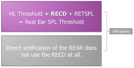
Figure 3. The RECD may be used behind the scenes in hearing aid fittings to predict real ear sound pressure level thresholds (pink box). Direct verification of the real ear aided response does not use the RECD.
If you are doing coupler-based verification, you are using the RECD in both cases, as shown in the pink box and the purple box in Figure 4.
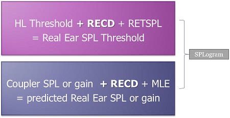
Figure 4. Diagram illustrating that coupler-based verification uses the RECD both in prediction of the real ear SPL threshold, and in prediction of real ear SPL or gain.
Consider fitting a BTE with an earmold, where you measured the RECD with the earmold. This lets you use that RECD to calculate predicted Real Ear SPL or gain in coupler-based verification (purple box). However, at the time of audiometry, you measured RECD using a foamtip to calculate Real Ear SPL Threshold (pink box). Now you have a mismatch; there are two different RECDs at play for this particular person as we go through the process of assessment to hearing aid fitting.
Recent practice surveys conducted in North America, mainly Canada and the US, show that there are a lot of different ways that audiologists are measuring RECDs in their assessment and fitting protocols (Moodie et al., in press a). Some audiologists measure RECDs with foamtips, while others measure them with earmolds. Some audiologists like to test children with earmolds during visual reinforcement audiometry (VRA) because they stay in the child's ears really well during head turns. Others like to use foamtips and not earmolds, because they want to use the standardized foamtip that was used to calibrate the transducer. There is good reasoning behind these various uses.
When we look at the results of this survey, the take home message is that a good software system needs to be able to deal with the diversity of protocols being used in practice. Even when only one protocol is used regularly, there may be exceptions that need to be taken into account. For example, if your protocol is to use earmolds for VRA testing, you may have some children on your caseload that don’t have earmolds yet, or have outgrown their earmolds, and need to be tested with foam tips. So, the fitting software and verification equipment need to account for earmold RECDs, foamtip RECDs, earmold audiograms, and foamtip audiograms.
Under the Hood #2: Coupling Type
We know from the literature that RECDs measured with foamtips and with earmolds are not the same (Bagatto et al., 2002; Moodie et al., in press b). The term for this is “coupling type”. The differences between RECDs measured with earmolds and RECDs measured with foamtips are mainly due to the tubing. Foamtips have about 25 millimeters of tubing but earmold tubing is usually much longer. An adult can have 50mm of earmold tubing, and even the tubing on earmolds of school age children are longer than the tubing on a foamtip. The longer the tubing, the more high frequency roll-off there is in the earmold response. So, the coupling type effect is that an RECD measured with an earmold is going to roll-off in the high frequencies compared to an RECD measured with a foamtip.
A clinical challenge presents when you need one type of RECD, but you have measured the RECD with the other coupling type. For example, if you conducted your audiogram using insert earphones with a foamtip, but you have measured your RECD with an earmold, you would have a mismatch in coupling type.
We know the age trends for both coupling types (Bagatto et al., 2002; 2005) and for that reason we embedded a prediction into DSL5. DSL5 will generate a predicted RECD for either coupling type as needed, based on the patient’s age. Sometimes the predicted RECD will be used instead of the measured one if the coupling type is not matched between RECD type and RECD usage (Bagatto et al., 2005). For example, DSL5 knows that a foamtip RECD is needed for the HL to SPL conversion with a foam tip audiogram. If only an earmold RECD is available, DSL5 will generate an age-predicted RECD for the foamtip for use in HL to SPL conversion. This is an example of a strategy that can be used when there is a mismatch between RECD coupling types.
In the rest of today’s talk, I’ll discuss a more individualized strategy for generating a predicted RECD that can step in if there is a mismatch in RECD coupling type as needed.
Under the Hood #3 – Coupler Type
Although the new ANSI standard uses only the HA1 coupler, conversions between the HA1 and HA2 couplers are simple, well-understood, and easily transformed by software.
For earmold RECDs, the standard calls for the earmold to be attached to the HA1 coupler, and while there are good reasons for that in the evidence, it does present some practical issues, mentioned above. Therefore, when measuring the coupler portion of the RECD, the HA2 coupler can be used, along with an HA1 to HA2 transform “under the hood” in the software that corrects between the two couplers. This has advantages when it comes to clinical ease because no putty is needed. As a result, there are fewer infection control issues, and you have a faster, more reliable connection to the coupler. There are also advantages when it comes to standardization; the standard HA1 RECD can be constructed and reported in the software even though you didn’t measure it that way. We refer to this “Coupler Type”.
Under the Hood #4 – Four Subtypes of RECD
If we combined both the Coupling Type and the Coupler Type, there are four possible subtypes of the RECD, as shown in Figure 5.
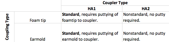
Figure 5. Four subtypes of RECD.
These subtypes have opposite advantages and disadvantages. For example, a foamtip RECD on the HA1 coupler is a standard RECD; while a foamtip on the HA2 is non-standard but doesn't require putty. An earmold on an HA1 coupler is standard and requires putty, while an earmold on an HA2 coupler is non-standard but does not require putty. For subtypes that use HA2 couplers, a conversion from HA2 to HA1 can be applied by the fitting software behind the scenes in order to have a standard RECD for data reporting purposes when it is needed, while avoiding the need for putty-based attachment to the HA1.
We can and do measure RECDs for all of these coupling types, but most people prefer to measure using an HA2 coupler in the clinic, because it is easier and cleaner. The clinical impact of this is that we need software systems that label RECD by subtype, so that the RECD can be corrected and used as needed.
For the sake of technical accuracy, there is a slight nomenclature difference that I will point out. The nonstandard RECDs (those measured using an HA2 coupler) are not technically supposed to be called RECDs according to the standard (ANSI, 2013). Instead, they are called ear-canal-to-coupler level differences (ECLDs). However, this term has not yet been implemented in clinically-available software systems, so I am using the term “RECD” for both RECDs and ECLDs in this article. The distinction between the two is important, and is aligned with the concept of RECD subtypes discussed above.
Under the Hood #5 – Transducer Effects
We know that RECDs differ by coupling type and by coupler. There are also interactions with the transducer type. In this discussion we are thinking about the earphone or any other sound source used to generate the signal during RECD measurement.
Historically, RECDs have been validated for the use of predicting the real ear aided response from coupler responses. The original method was proposed by Moodie and colleagues in 1994. A validation study looked at the accuracy of this procedure across a group of patients (Seewald et al. 1999). This was replicated by another laboratory in the UK (Munro & Hatton, 2000). All of these studies showed good agreement between the measured real ear gain or output and the predicted real ear gain or output when the RECD was used to build a conversion between the two.
All of these studies were done using ER3 insert earphones and occluding earmolds for the RECD measures. In this context, the procedure is well validated. However, a concern arose because sometimes the clinical RECD may be different than the RECD for the hearing aid or for the insert phones. Munro and Salisbury (2002) measured RECDs both with a clinical RECD transducer and with ER3A insert phones. They found a difference between the two by 9 dB at 1.5 kHz, which is more than what was previously reported in the literature. They also noticed that this only happened with longer tubing lengths, which happened to be about the same as an adult earmold tubing length of 45 millimeters.
In a follow-up study, Munro and Toal (2005) looked at the implications for hearing aid fitting. Their RECDs varied with the type of hearing aid. Across different models of hearing aids, they were seeing different degrees and types of error. In both of these studies, if the RECD was measured with a clinical transducer that had low impedance, there was more error. This new factor was puzzling for all of us who work within this area, and so follow up studies were done to try and understand it further.
One of the things we learned from our studies at UWO (e.g., Bagatto et al., 2005) is that we can minimize these transducer effects if we have short ear mold tubing. In other words, the transducer effects are less if earmold tubing is short.
Figure 6 shows an example using a 35mm earmold tubing.
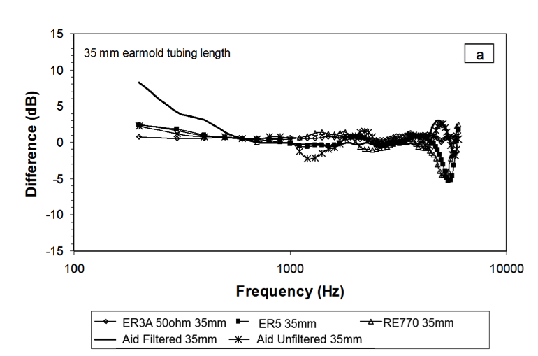
Figure 6. Results from Bagatto et al., 2005, showing that transducer effects are small when earmold tubing is short.
In Figure 6, you can see a dip at 1500 Hz for the RECD that was measured with a hearing aid with an unfiltered ear hook. With a filtered earhook and a short tubing length, the amount of error that is observed is quite small. Aside from some possible slit leak effects in the low frequencies and some minor probe tube placement issues, the majority of the frequency responses from the hearing aid in this graph show similar RECDs across transducer types for an earmold with 35mm tubing length. That is encouraging.
With a 45 millimeter tubing length, there are larger amounts of error that replicate the Munro data (Figure 7). The RECDs are different across transducer types, mainly in the 1250 Hz to 1500 Hz region. However, when the hearing aid has a filtered earhook, the error is less, as shown by the heavy black line in Figure 7. While there is some error, it is within a few dB when the earhook is filtered.
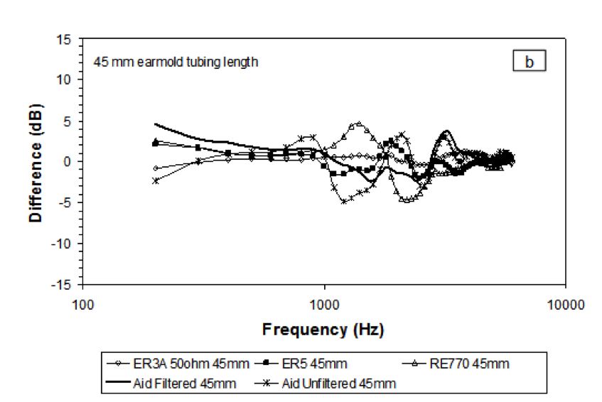
Figure 7. Data from Bagatto et al. (2005) showing results with 45mm tubing length.
These are fairly complex issues. We see peaks and valleys in a frequency response due to the interaction between tubing length on a coupler, tubing length in the earmold, the impedance of the transducer, and we also observe how the impedance of the transducer is changed by filtering the earhook. While I won’t go into more detail on these specifics today, my point in reviewing this is to alert you to the fact that there are some underlying issues that were considered by the ANSI Standards committee.
If you look at these data, the frequency range where most of the errors are occurring is a frequency range that is impacted by tubing length differences. The difference between the length of the fixed earmold tubing simulator on an HA2 coupler and the actual earmold tubing length is where error occurs, that is where the impedance of the HA1 and HA2 transducers differs.
Using the HA1 coupler as the standard helps to handle these types of challenges in RECD accuracy. Munro & Toal (2005) compared RECDs defined in the HA1 coupler versus the HA2 coupler. While there were some mid-frequency issues in both cases, there was far less with the HA1 coupler. These results, in part, explain why the HA1 coupler is used in the standard. This is an important issue in terms of accuracy. Clinically, it also important for measurements to be feasible in day to day practice. We need our software systems to take this issue into account.
New Software Functions for the RECD
Now I’ll discuss new software functions associated with measuring and applying the RECD that were developed with a goal of complying with the new standard. These new functions were also developed to support the wide range of clinical practice protocols and clinical scenarios that we encounter. These software functions are specific to Audioscan systems.
Given what we have learned as RECD has developed over the years, including the new evidence on the difference between foamtip and earmold RECDs, there are three protocols that I typically teach to my students. These protocols include matching the type of RECD that you need to how you have assessed the person and how they are being fitted with hearing aids.
Protocol #1: Audiometry with insert phones/foamtip + RECD with foamtip + Verification in Real Ear
In the first protocol, audiometry is done with insert phones and the insert phones were coupled to the ear using a foamtip. Since a foamtip is coupled to the ear for the HL to SPL transform, we measure the RECD with a foamtip. Using a foamtip for both the assessment and the RECD gives us a match, ensuring that the HL to SPL transform is correct. Earmold acoustics are accounted for during verification, so we don't need an earmold RECD. Since we are using the earmold during the verification, the venting, tubing and other acoustic properties will be represented in the real ear measurement.
This is a good protocol for use with adults, or anyone who can sit and be compliant for a real ear measurement. It a great strategy for vented fittings, because if there is a vent in the earmold it will be reflected in the real ear verification. It is good to use for fitting custom hearing aids, and it is easily modified for use with CROS and Bi-CROS fittings (Pumford, 2005). This protocol can be a “go-to” protocol for use with adults and older children, but for fitting hearing aids to babies it is not feasible.
Protocol #2: Audiometry with insert phones/earmolds + RECD with earmolds + Verify BTE in HA2 coupler
At our clinic, we often test babies using insert phones plus earmolds. Earmolds stay in well for VRA. We measure the RECD with their earmolds so that we have a match between the RECD coupling type and the assessment coupling type. We verify the BTE hearing aid using coupler-based verification, which also uses the earmold RECD to account for earmold tubing length. This protocol works well for babies and young children who typically have little or no venting in their earmolds, and are unlikely to sit for real ear measurement. We don't need to have a real ear procedure for assessing venting in these cases as the earmolds are generally not vented. Therefore, this is a good protocol for individualization of hearing aid responses in small ears, accounting for both unvented earmold acoustics and ear canal acoustics.
Protocol #3: Audiometry with insert phones/foamtip + RECD with foamtip + Verify with HA1 Coupler
A variation of this protocol can be used when fitting hearing aids to adult patients and the patient is not available for real ear measurement. We can use this protocol to verify a custom product or a Receiver-in-Canal product in the HA1 coupler. We can convert insert phone audiograms with foamtips using a foamtip RECD to customize the HL to SPL transform. Then, that same RECD is used to convert measures made in the HA1 coupler to predicted real ear sound pressure level.
Note that we avoid RECD mismatches in all of these three protocols. Use of these protocols is best if clinicians understand that matching is part of the goal of creating a good, accurate protocol.
Mismatching
While we know the importance of matching, it is not always possible in everyday clinical practice. Consider this scenario: audiometry is conducted with insert phones and a foamtip, the RECD is measured with an earmold, and verification is done with the BTE using the HA2 coupler. In this case, the earmold RECD is a good match for converting the hearing aid data from the HA2 coupler to predicted real ear sound pressure level. However, it is not a good match for converting the insert phones audiogram, because it was measured with foamtips. What can be done in this case?
New Software Systems Support Corrections to Handle Mismatches
New software systems allow us to label the RECD sub-type. By indicating the type of RECD we measured, the software can apply corrections that handle mismatches if they occur (Moodie et al., in press a). However, a software system can handle a mismatch only if it knows that there is indeed a mismatch, so we need to label our transducer types, coupler types, and RECD types. This is easy to do in software by simply inputting a few additional pieces of information.
In addition to the information you have selected in the past, you will now label the type of coupler-based fitting you will use for coupler-based verification, as either HA1 or HA2 (see top arrow in Figure 8). In addition, you will label the type of RECD you are measuring or entering as either earmold or foamtip (see bottom arrow in Figure 8). Simply enter what you did.
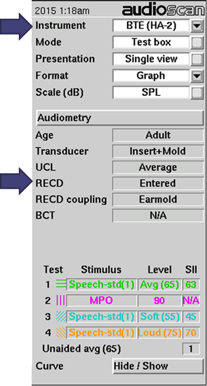
Figure 8. Software screen from Audioscan specifying RECD parameters.
These pieces of information will be used behind the scenes to define whether you have a match or mismatch for either use of the RECD and to enable the software to take that into account. If necessary, the software will convert between foamtip and earmold RECDs using a new correction procedure. If you enter a matched protocol, no corrections will be applied by the software. Preliminary data suggest that accounting for a mismatch may be more accurate than using age-predicted averages (Moodie et al., in press a).
With some Verifit systems (Verifit, Axiom, and SL) you can use the HA2 coupler for measuring the coupler portion of the RECD. This is called “RECD transducer calibration". As a short form, you will sometimes see the word “Xducer” used to mean “RECD Transducer Calibration” in the software. When you use the HA2 coupler, the values will get converted to HA1 later by the software, so that the result is a standard RECD, even though you didn’t measure it that way. You can use either the foamtip or the earmold depending on the protocol you are following and what you have available.
So when will corrections be used and how? If you measure a foamtip audiogram along with a foamtip RECD, the HL to SPL transform will be calculated as it always has been (Figure 9, left side). This is nothing new. However, consider what happens when you have a foamtip audiogram and an earmold RECD, as illustrated in the right hand column in Figure 9. Now, the software system knows that this is a mismatch. It will apply an earmold to foamtip correction (Moodie et al., in press a) to convert the measured earmold RECD to a predicted foam tip RECD. This individually-predicted foamtip RECD will then get used in the HL to SPL transforms. This is new.
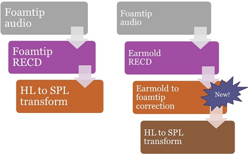
Figure 9. Converting foamtip audiograms from HL to SPL – using a foamtip RECD on the left, and using an earmold RECD and new software corrections on the right.
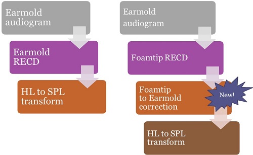
Figure 10. Converting earmold audiograms from HL to SPL – using an earmold RECD on the left, and a foamtip RECD along with new software corrections on the right.
Now consider what happens when you have an earmold audiogram (Figure 10). Perhaps you had the earmolds connected to the insert phones during VRA, and obtained HL thresholds. Historically, if you had measured an earmold RECD, that would have been used to build your HL to SPL transform, and you can see this protocol on the left hand side of Figure 10. That is not new. On the right hand side of Figure 10, we have measured an earmold audiogram and a foamtip RECD. That is a mismatch. The software will now know there is a mismatch, and it will apply the foamtip to earmold correction to convert the foamtip RECD to a predicted earmold RECD. The predicted earmold RECD will be included in the HL to SPL transform.
Now let’s look at verification (Figure 11).

Figure 11. Test box verification using a BTE with the HA2 coupler: using the earmold RECD (left); using the foamtip-to-earmold correction available in new verification software (right).
Let's say we are doing a typical pediatric verification protocol with a BTE on the HA2 coupler for coupler-based verification. Audioscan products filter the microphone location effect into the test signal and historically would have added the earmold RECD to the coupler curves to convert them to predicted real ear SPL. Then predicted real ear SPL is then displayed on the SPLogram (Figure 11, left side) and that is not new. What is new is represented on the right hand side of Figure 11. Now, if you need an earmold RECD to build the prediction from the HA2 coupler to the real ear for a BTE user, but you only have a foamtip RECD, the software will recognize that. It will apply the foamtip to earmold correction, build an individually predicted earmold RECD, and then use that to build the HA2 to real ear transform.
The new functions in all of these examples are being done automatically and as needed, based on what you enter in the more detailed menu settings. In the past, if you were fitting a hearing aid and needed an earmold RECD, the software would have predicted it based on the person’s age (Bagatto et al., 2005). Now, the software will predict foamtip RECDs from measured earmold RECDs or vice-versa, using a new correction for foamtip-to-earmold differences (Moodie et al, in press a, Figure 12). This is more of an individual prediction than simply using the chronological age.
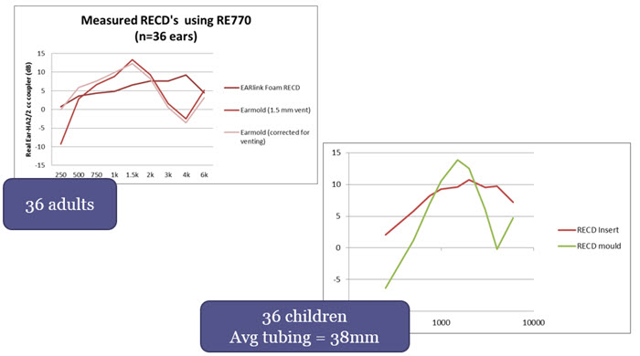
Figure 12. Dataset used to determine earmold to foamtip corrections (adapted from Moodie et al., in press a).
In the adult curves (Figure 12), you will see we measured foamtip RECDs, as well as vented and non-vented earmold RECDs. Figure 12 shows the mean RECDs averaged across the 36 adult ears. Regardless of the venting effects, earmold RECDs have more mid-frequency resonance and more roll off in the high frequencies, compared to foamtip RECDs. There is a substantial difference in opposite directions in the mid and the high frequencies between a foamtip RECD and an earmold RECD.
The children had an average tubing length of 38 millimeters. If you look at the mean RECDs averaged across the kids, there is a similar pattern to the adult data. For both groups, we calculated the difference between the earmold RECDs and foamtip RECDs across frequencies. This was compared to a proposed correction (from simulated ears) that is applied to convert between foamtip and earmold RECDs.
Protocol #4: Audiometry with insert phones/foamtip + measured RECD with earmolds + Verify BTE in coupler
The best accuracy is likely still obtained with matching protocols, such as the three protocols presented above. However, now we have a good fourth option if we have mismatches. In this protocol, we can use the earmold RECD for coupler-based verification, and automatically generate an individually predicted foamtip RECD for the HL to SPL transformation of thresholds. This is expected to do a better job of predicting the HL to SPL transformation, possibly improving accuracy compared to using an age-predicted transform (Moodie et al., in press a).
If you use protocol #4, there are a few potential clinical impacts. The first is possible earmold notches in the verification curves. One common pediatric protocol is conducting audiometry with insert phones and foamtips, measuring the RECD with a foamtip, and verifying the BTE hearing aid on an HA2 coupler (Moodie et al, in press b). An example of verification curves obtained using this protocol is shown in Figure 13.
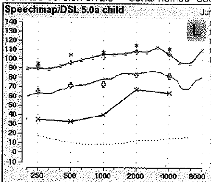
Figure 13. Curves demonstrating that a notch in the high frequency region of verification curves may result when a foamtip audiogram and foamtip RECD are used to verify a BTE hearing aid on the HA2 coupler.
In newer versions of Audioscan software, this protocol will now include the foamtip to earmold correction to convert the measured foamtip RECD to a predicted earmold RECD for use in verification. This shows up as a notch in the high frequency region (Figure 13) that may not have been present during verification with older software. In this case the notch is due to the high frequency roll-off of the earmold tubing. We would recommend fine-tuning to remove the notch if possible.
Which Software Versions Implement the New RECD Standard?
It’s important to understand which versions of software systems implement this correction. Depending on what version of software you are using, you may need to update your software to have this functionality. Verifit and similar systems version 3.12 and later, as well as Verifit 2 and similar systems version 4.2 and later support the new RECD procedure; there is support for HA2 or HA4 couplers, as well as new foamtip to earmold conversions. It is these latest versions that we recommend for clinical use.
Prior to 2014, software versions 3.10.56 and earlier included the RECD implementations that we have used for years; these versions were prior to the new ANSI RECD standard. In software versions 3.10.56 – 3.10.70. the new RECD standard was implemented but there was some requirement to use the HA1 coupler and putty. This has since been updated and replaced with the RECD procedures described in this article.
Using Verifit 2 for the new RECD Procedure
Use the Silver Coupler Set for Fitting to Targets
With Verifit 2 (VF2), there are two different coupler sets; a blue set and a silver set. The silver coupler set (two couplers) is intended for use in fitting to targets and RECD measurement. The blue coupler (one coupler) is a 2cc coupler; it is for ANSI tests only. The silver set uses a smaller coupler volume, 0.4cc, and is the only coupler type that should be used in the “Speechmap” area. If you measure a hearing aid in both coupler types, the response obtained with the silver coupler will exceed the response obtained with the blue coupler by about 20 db. If, in error, you fit a baby's hearing aid on the blue coupler, you will overamplify by about 20 db. It is critical to use the silver coupler, and not to use the blue coupler when fitting to target.
In our clinic, we have a lot of people in training. I wanted it to be very clear to everyone and ensure that we don’t make a mistake in coupler selection, so I labeled our couplers. I would strongly recommend viewing this video on coupler set ups. A recent online article describes new RECD procedures and coupler-based verification for VF2 and Verifit (Glista, Hawkins, Moodie, and Scollie, 2015), with photos of key setups.
The video shows you how to set up the silver couplers for both ears at the same time, how to set up the coupler for use with RIC instruments, and includes other valuable information.
Wideband RECDs (WRECDs)
On the Verifit 2, RECDs are measured as referenced to the new 0.4 cc coupler. They are not referenced to an HA2 coupler. That is an important between-system difference.
Because they were intended to be measured across a very wide range of frequencies, they are called wideband RECDs or WRECDs. The table of values will show you both a standard 2cc HA1 RECD as well as the WRECD, because a known transform can convert back and forth between the two formats.
BTE Hearing Aid Verification: HA4 Coupler Replaces HA2 Coupler
In Figure 14, you will see the HA4 coupler.
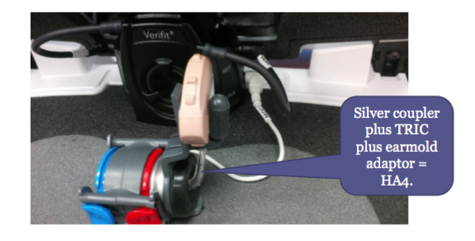
Figure 14. The HA4 coupler in the Verifit 2 consists of the silver 0.4cc coupler, a TRIC adaptor, and a piece of earmold tubing.
The HA4 coupler consists of the silver 0.4 cc coupler, a black soft adapter (called a TRIC adaptor) that snaps onto it much like a Tupperware lid, and a small piece of standard length earmold tubing. This combination of pieces is referred to as an HA4 coupler, and is similar in concept to an HA2 coupler. It uses the TRIC adaptor and tubing as the earmold simulator rather than the stepped bore earmold simulator on the HA2.
You can also use a similar setup to verify slim tube and RIC devices in the coupler. Instead of using the earmold tubing, you would insert the end point of the device into the TRIC adaptor. The intended purpose of the TRIC adapter is to enable an easy way to connect slim tube and RIC devices onto the coupler without having to use putty.
Case Examples
I am going to review a few case examples from our testing, where we tested for consistent verification results across software updates, verification systems, and coupler verification versus real ear verification, with the new corrections in place.
Example #1: Are Verification Results Consistent Across Software Updates?
Coupler Verification Pre vs. Post the New RECD Standard. The first case looks at the issue of consistency across software updates. In Figure 15, you will see two sets of results. In the top panel are coupler verification results for a BTE using an older software version (Version 3.10.39) that were measured before the new ANSI RECD standard was issued. In the bottom panel are results for that same fitting verified using software version 3.12 that includes the new ANSI RECD standard and the corrections we discussed today.
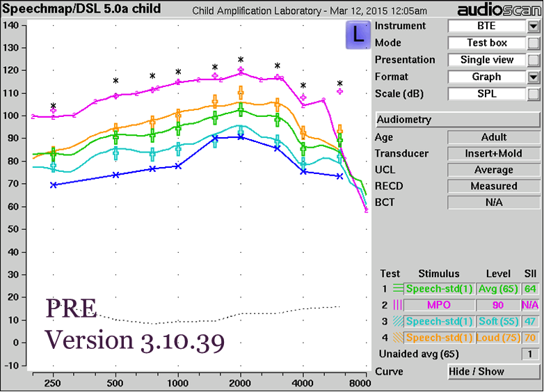
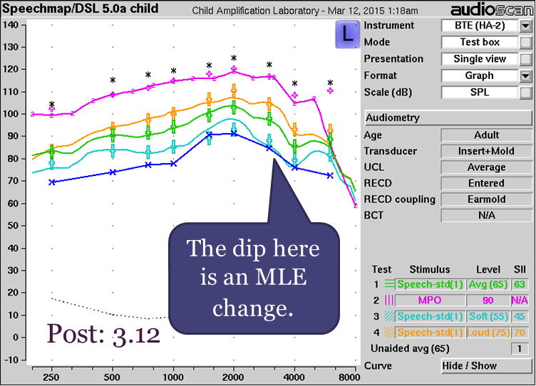
Figure 15. Coupler verification pre- versus post the new RECD standard with BTE. Top panel results were obtained prior to the new RECD standard using an older software version; bottom panel results were obtained using software that is updated to the new RECD standard.
When you compare the results in both panels, you will see that they are highly consistent. There is a small difference between the two sets of results where indicated by the purple arrow in the bottom panel. This difference is not related to the RECD changes discussed in this article; it is a result of an updated set of microphone location effect (MLE) values in the software. These new MLEs mostly affect soft speech; with average speech or higher they are compressed by the hearing aid and the differences between systems are less apparent.
Example #2: Does Test Box Verification Accurately Predict On-Ear Output for a BTE?
In this example, we fitted a BTE hearing aid on the ear, and then took measurements in a test box, to determine whether coupler-based verification accurately predicted on-ear results. In Figure 16, the curves in the left panel are a real ear aided response measured directly for an adult with long earmold tubing. This is the kind of test case that might be of concern based on the literature reviewed earlier in this article. The curves in the right panel were measured using Verifit version 3.12, with the real ear aided response predicted from the coupler-based measures using the RECD.
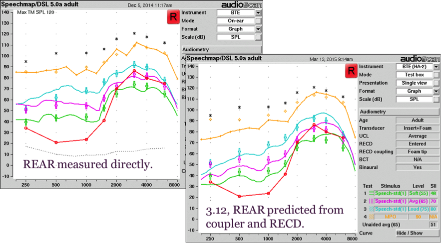
Figure 16. REAR (left panel) versus coupler-based verification (right panel) with new RECD standard for a BTE.
You can see in the figure that for the coupler verification, the transducer type entered was “insert plus foam” and the RECD coupling type was “foamtip”. So, this measurement includes the foamtip to earmold correction. Keep in mind that the test box measures are a prediction of what is happening in the real ear. The agreement between the two measures are fairly close. Differences can be due to prediction errors, venting effects especially in the low frequencies, probe tube placement and room reflections.
Test Box Verifit 1 versus On Ear Verifit 1. We are also interested in between-system agreement: the corrections should work well in both the HA2-based Verifit (VF1) and the 0.4 cc coupler-based VF2. Here is an example using BTE hearing aids verified in the test box compared to those same hearing aids verified on ear with a Verifit 1.
You can see the results in Figure 17.
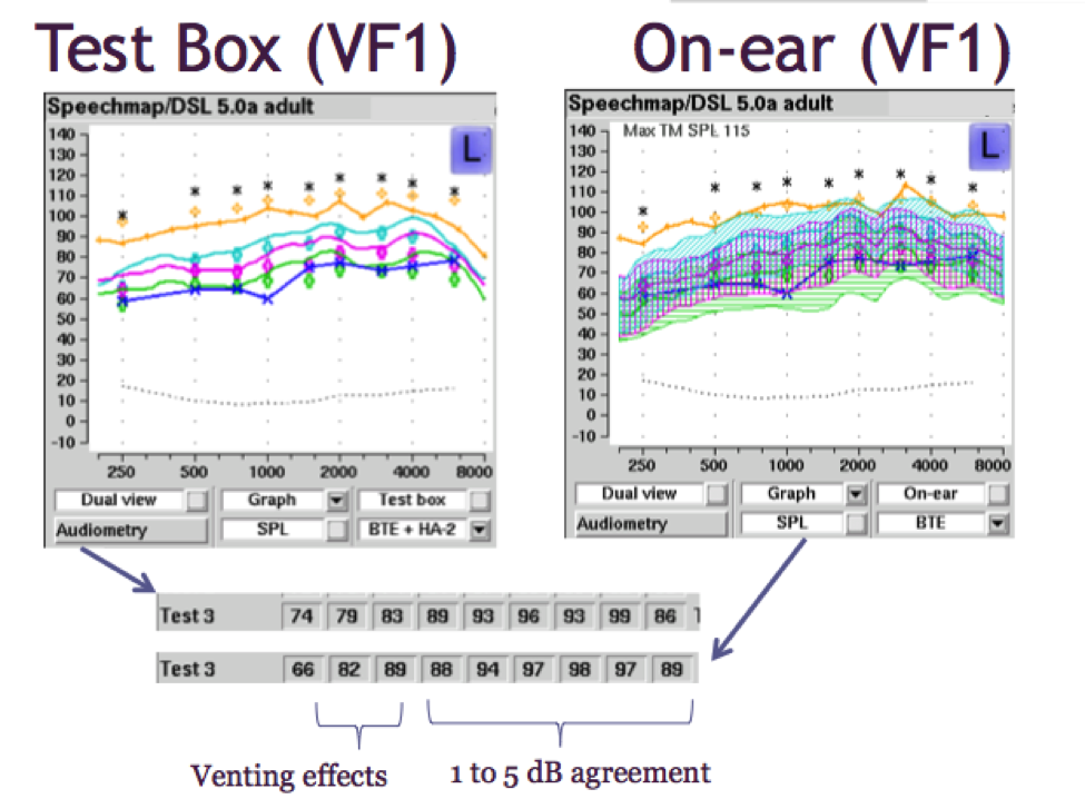
Figure 17. Test box versus on-ear verification for a BTE using Verifit 1.
On the bottom of Figure 17, I have pulled out the data from the Verifit so that you can compare them easily; the results from the test box are on top, and the results from on-ear measures are on the bottom. When you compare these two sets of numbers, you’ll note differences of 1 dB to 5 dB for the mid to high frequencies, and slightly more differences in the low frequencies due to venting effects. These measures were from an adult with clinically typical venting.
As we can see from this example, sometimes there are differences in the low frequencies due to venting effects. Venting effects will be more accurately tested on-ear than they would be in a test box simulation since venting is not represented in coupler verification. It is not possible to vent into a coupler at this point. We do not expect test box verification to necessarily take into account everything that we know would be represented about venting, and for that reason, on-ear measurement would be considered the gold standard in this particular scenario.
Other than the venting issue, we have an accurate representation of the fitting in the test box as compared to the on ear fitting using the Verifit 1.
Test Box Verifit 2 versus On Ear Verifit 2. We repeated the testing using Verifit 2 for the same patient, and the results are shown in Figure 18. The curves on the top were obtained in the test box using the HA4 coupler and those on the bottom were obtained on-ear.
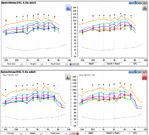
Figure 18. Results from Verifit 2 for a BTE hearing aid: Test box verification (top) and on-ear verification (bottom), for both left and right ears.
Visually, we note that in comparing the test box and on-ear measures for both the left and right ears of this patient, the characterization of the fitting is similar.
Example #3: Verification Agreement Between Systems
Verifit 1 versus Verifit 2 (Test Box Verification with BTE). This example looks at agreement between results from the Verifit 1 compared to those from the Verifit 2. The results for test box verification for a BTE hearing aid are shown in Figure 19, with Verifit 1 results on the left and Verifit 2 results on the right.
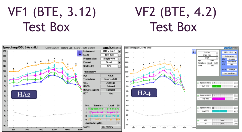
Figure 19. Test box verification with a BTE using Verifit 1 (left panel) and Verifit 2 (right panel).
Here we have good agreement between these systems, but it’s important to note the software versions that were used. I have noted the software versions in the figure. To obtain the kind of agreement you see here, it is important to ensure that you have compatible software systems so that you are comparing “apples to apples”.
Verifit 1 versus Verifit 2 with Receiver-in-the-Ear Hearing Aid. Our current project involves testing other hearing aid styles in addition to BTE models. It is interesting to have a look at receiver in the ear canal styles, referred to as RIC (receiver-in-canal) or RITE (receiver-in-the-ear) devices.
Figure 20 shows on-ear verification of a RITE device using the VF1 as compared to the VF2.
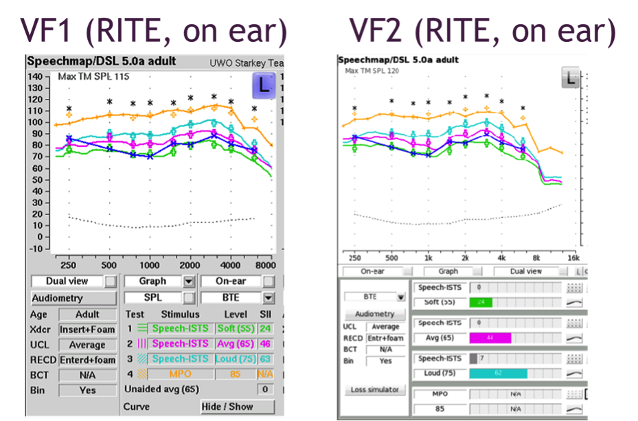
Figure 20. On-ear verification of a RITE hearing aid with Verifit 1 (left panel) and Verifit 2 (right panel) for one patient.
Figure 21 shows results obtained from measuring that same device in the test box of both VF1 and VF2.
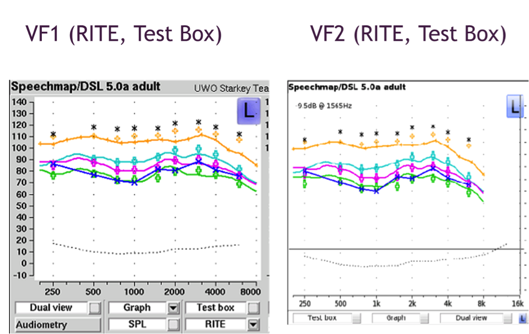
Figure 21. Test box verification of RITE hearing aid using Verifit 1 (left panel) and Verifit 2 (right panel).
In test box verification, VF1 uses the HA1 coupler and putty, while VF2 uses the TRIC adaptor and the 0.4cc coupler. As shown in figures 20 and 21, we have good agreement between the two systems in both on-ear and test box measurements, which are encouraging findings.
Additional Notes
If you are going to conduct these comparisons yourself, we have learned a few things that I included in Figure 22. While I won’t get in to the details here, these are some considerations that can help to ensure that the match between systems is as close as possible.
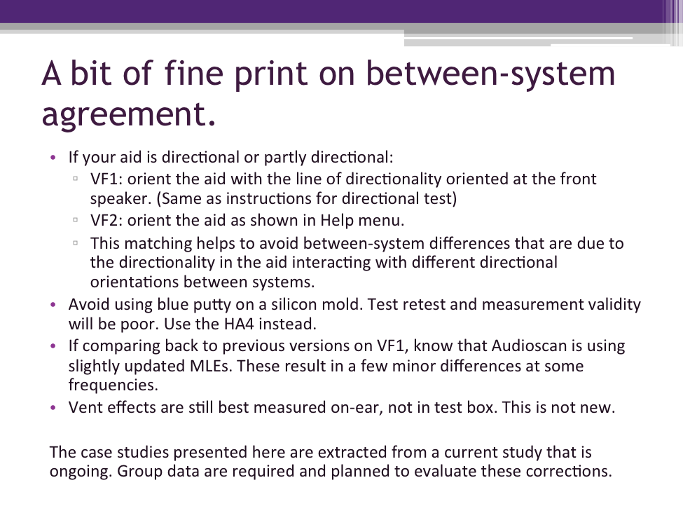
Figure 22. Considerations for comparisons of results between systems.
The cases discussed today have been extracted from a current study that is ongoing. Obviously, group data is needed to have a full evaluation, and we are working towards that.
We have evaluated these corrections mainly on earmolds of 31 millimeters or longer. This is why the “Help” menu in the Audioscan systems currently recommends entering “foamtip” for earmolds less than 35mm. However, there are not a lot of data right now on very young babies comparing foamtips versus earmolds, so I will acknowledge that as a limitation at this time.
Evaluations are underway with BTE, ITE, and RIC models. Our BTE fittings have what we call “clinically typical venting”, and are fitted to adults. As is often the case with research, further work is necessary.
Summary
We know from the past 15 years or so of research on real ear measurement that it is reliable and accurate. We also know how to use RECD-based predictions when direct real-ear measures are not feasible. Studies have continued to evolve our knowledge about real ear measurement and how to optimize it, and much of that knowledge has been incorporated into the new ANSI standard. There is a strong evidence base for the new parts of the standard. We also understand that flexibility is needed for clinical practice, because there are many different protocols in use by clinicians. This article summarizes some software developments that have considered both of these issues.
If you use an Audioscan system in your clinic, check your software version and update it if necessary, especially if you use RECD. This set of procedures is what we actively use in our laboratory and clinic and what we recommend for clinical use with Audioscan systems.
In general, any system that fully labels the RECD by coupling type and coupler type is already making either age-based corrections or foamtip-to-earmold corrections. Your best contribution to accuracy is to measure the RECD and label it correctly in the software, so that the software has the information it needs to make corrections when and if necessary.
Thank you for taking the time to learn about this topic. I hope the information is helpful in ensuring your fittings are accurate and beneficial for the patients you serve.
References
Aarts, N.L., & Caffee, C.S. (2005). Manufacturer predicted and measured REAR values in adult hearing aid fitting: accuracy and clinical usefulness. International Journal of Audiology, 44(5),293-301.
Aazh, H., & Moore, B.C.J. (2007). The value of routine real ear measurement of the gain of digital hearing aids. Journal of the American Academy of Audiology, 18,653-664.
Adkins, C. (2014). Infection control in audiology. Retrieved from: https://prezi.com/w1eitoiu62z1/infection-control-in-audiology/.
American Academy of Audiology. (2013). American Academy of Audiology Clinical Practice Guidelines: Pediatric Amplification. Retrieved from https://audiology-web.s3.amazonaws.com/migrated/PediatricAmplificationGuidelines.pdf_539975b3e7e9f1.74471798.pdf
American Academy of Audiology Task Force. (2006) Guidelines for the audiological management of adult hearing impairment. Audiology Today 18(5), 32-36. Retrieved from https://audiology-web.s3.amazonaws.com/migrated/haguidelines.pdf_53994876e92e42.70908344.pdf
American National Standards Institute (1997). S3.46-1997, Methods of measurement of real-ear performance characteristics of hearing aids.
American National Standards Institute (2013). S3.46-2013, Methods of measurement of real-ear performance characteristics of hearing aids.
Bagatto, M., Moodie, S., Scollie, S., Seewald, R., Moodie, K., Pumford, J., & Liu, K.P.R. (2005). Clinical protocols for hearing instrument fitting in the Desired Sensation Level method. Trends in Amplification, 9(4), 199-226.
Bagatto, M.P., Scollie, S.D., Seewald, R.C., Moodie, K.S., & Hoover, B.M. (2002). Real-ear-to-coupler difference predictions as a function of age for two coupling procedures. Journal of the American Academy of Audiology, 13, 407-415.
Bagatto, M., Moodie, S., Brown, C., Malandrino, A., Richert, F., Clench, D. and Scollie, S. (2016). Prescribing and verifying hearing aids applying the American of Academy Pediatric Amplification Guidelines: Protocols and outcomes from the Ontario Infant Hearing Program. Journal of the American Academy of Audiology, Retrieved from: https://aaa.publisher.ingentaconnect.com/content/aaa/jaaa/pre-prints/content-AAA_JAAA_15-051
Glista, D., Hawkins, M., Moodie, S., & Scollie, S., (2015). Clinical changes to RECD M=measures: Understanding how the RECD fits into the “big picture” of hearing aid fitting. Canadian Audiologist, 2(6). Retrieved from: https://canadianaudiologist.ca/issue/volume-2-issue-6-2015/
Kemp, R.J., & Bankaitis, A.U. (2000). Infection control in audiology. AudiologyOnline, Article 1299. Retrieved from: https://www.audiologyonline.com
Kochkin S., Beck D.L., Christensen L.A., Compton-Conley C., Fligor, B.J., Kricos, P.B.,...Turner, R.G. (2010). MarkeTrak VIII: The impact of the hearing healthcare professional on hearing-aid user success. Hearing Review, 17, 12–34.
McCreery, R.W., Bentler, R.A., & Roush, P.A. (2013). Characteristics of hearing aid fittings in infants and young children. Ear & Hearing, 34(6), 701-10.
Moodie, K.S., Seewald, R.C., & Sinclair, S.T. (1994) Procedure for predicting real-ear hearing aid performance in young children. American Journal of Audiology, 3, 23-31.
Moodie, S., Pietrobon, J., Rall, E., Eiten, L., Lindley, G., Gordey, D., Davidson, L.,…Scollie, S. (in press a). Using the Real-Ear-to-Coupler Difference within the American Academy of Audiology Pediatric Amplification Guideline: Protocols for applying and predicting earmold RECDs. Journal of the American Academy of Audiology.
Moodie, S., Rall, E., Eiten, L., Lindley, G., Gordey, D., Davidson, L.,…Scollie, S. (in press b). Applying the AAA Pediatric Amplification Guidelines: Survey of current practice. Journal of the American Academy of Audiology.
Mueller, H.G. (2014). 20Q: Real-ear probe-microphone measures – 30 years of progress? AudiologyOnline, Article 12410. Retrieved from: https://www.audiologyonline.com
Mueller, H.G. (2015). Speech mapping – clinical tips. AudiologyOnline, Article 21160. Retrieved from: https://www.audiologyonline.com
Munro, K.J., & Hatton, N. (2000). Customized acoustic transform functions and their accuracy at predicting real-ear hearing aid performance. Ear & Hearing, 21(1), 59-69.
Munro, K.J., & Salisbury, V.A. (2002). Is the real-ear to coupler difference independent of the measurement earphone? International Journal of Audiology, 41(7), 408-13.
Munro KJ, & Toal S. (2005). Measuring the RECD transfer function with an insert earphone and a hearing instrument: are they the same? Ear & Hearing, 26, 27-34.
Pumford, J. (2005) Benefits of probe-mic measures with CROS/BiCROS fittings. The Hearing Journal, 58(10), 34-40.
Pumford, J., & Sinclair, S. (2001). Real-ear measurement: Basic terminology and procedures. AudiologyOnline, Article 1229. Retrieved from: https://www.audiologyonline.com
Saunders, G,H,, & Morgan, D.E. (2003). Impact on hearing aid targets of measuring thresholds in dB HL versus dB SPL. International Journal of Audiology, 42, 319-326.
Seewald, R.C., Moodie, K.S., Sinclair, S.T., & Scollie, S.D. (1999). Predictive validity of a procedure for pediatric hearing instrument fitting. American Journal of Audiology 8(2),143-152.
Seewald, R.C., Moodie, S., Scollie, S.D., & Bagatto, M. (2005). The DSL Method for pediatric hearing instrument fitting: Historical perspective and current issues. Trends in Amplification, 9(4), 145-157.
Cite this Content as:
Scollie, S.D. (2016, February). New RECDs and a new ANSI standard: Revisiting RECD basics and applications. AudiologyOnline, Article 16380. Retrieved from https://www.audiologyonline.com.