This is a transcript of a live webinar. Download supplemental course materials.
Talking about the telecoil is something that is relatively new to me. About two years ago a student wanted me to be a mentor for a Capstone project and we eventually came up with a project dealing with the telecoil. Prior to that, I had knowledge of telecoils, of course, but I did not think that much about it. Since that project two years ago, the telecoil and its operation piqued my interest. In today’s presentation, you may find I’m asking more questions than providing answers, which I think is a healthy exercise. I will also introduce perhaps one or two new concepts.
The telecoil is not exactly the most exciting topic in the world, to most people. I thought that same thing two years ago as well. However, sometimes things that you think are not very exciting turn out to be pretty important, and this is one of those times.
Here is the outline of what I hope to accomplish. As an introduction, I will briefly discuss Looping America, which is an initiative that started about two years ago. Then we will talk about the ability to loop homes as part of audiology services. I will show an example of an actual telecoil for those who may have never seen one. Believe it or not, it is not uncommon for audiologists never to have seen a telecoil. Next, we will talk about the orientation of the telecoil for both telephone and hearing assistive technology. Then I will give you my thoughts and some questions I have come up with for future research projects. I will also cover how we objectively measure telecoil performance utilizing the coupler relative to the American National Standards Institute (ANSI) 2003 and 2009 standards. I will also throw out the idea of measuring telecoil performance in the real ear, which was the Capstone project that we did two years ago. That is something that I think is coming forward into the future. We will talk about what options are available to you as clinicians for programming a telecoil and why you might want to do that. Lastly, we will talk about some of the research projects that my colleague, Kristi Oeding, and I are working on with students here at Washington University in St. Louis.
Recently, there has been a surge of interest in the importance of the telecoil due to the American Academy of Audiology and the Hearing Loss Association’s joint campaign to Loop America, which, frankly, is well behind Europe and other countries. This initiative started back at Audiology NOW! in 2010 and seems to be picking up steam. In fact, if you were to look at the most recent issue of the Hearing Journal, there is an article called “A Surge in Hearing Loops Gives Hearing-Impaired Front Row Seats” (Shaw, 2012). It is a quick read and an interesting article on where we are and where we are headed in the future with the looping of America.
There are many examples of places that are looped in the United States. These include: the main chamber of the House of Representatives, homes, workplaces, entertainment venues, places of worship, courtrooms, ticket counters, information booths at a wide variety of museums and other venues, physician offices, pharmacy counters, elevators, trains, taxis in New York City, buses, transportation, food and dining, and education. At Washington University, we have three counseling rooms that are looped. Looping is all over the place.
When I started to become interested in this topic, I was curious who in the St. Louis area provided looping for our patients. I found www.loopAmerica.com. When you go to that site, you will find a map. I clicked on Missouri to find looped venues in the state. According to this Web site, the only place that did looping was all the way over toward Kansas City. There was nothing available in the St. Louis area. That was the catalyst for us here at Washington University to create and provide looping for our patients, as well as for anyone in the St. Louis area that might be interested.
One of our audiologists and her husband have looped several homes, churches and a wide variety of other venues in the St. Louis area. A year-and-a-half ago, this was not available at all in the St. Louis area. I had a patient who was having significant difficulty in his home office. We had the loop in our office, and I turned it on. He thought this was the best thing since sliced bread. I introduced him to our audiologist, who then made arrangements with her husband to loop his home so he could be a more effective accountant on the telephone and have better clarity listening to the TV in his office. It has made a positive impact on this gentleman’s life. To watch that occur in a relatively short period of time was an altering experience. Prior to that, he was struggling with utilization of the microphone and the telecoil in his office without the loop. That changed for him in just half a day. It made me wonder why I was not doing this in the past.
All of you should be familiar with the induction loop system (Figure 1). You have any auditory input going to an amplifier that creates a loop and is directly transmitted to the telecoil of the person’s hearing aid.
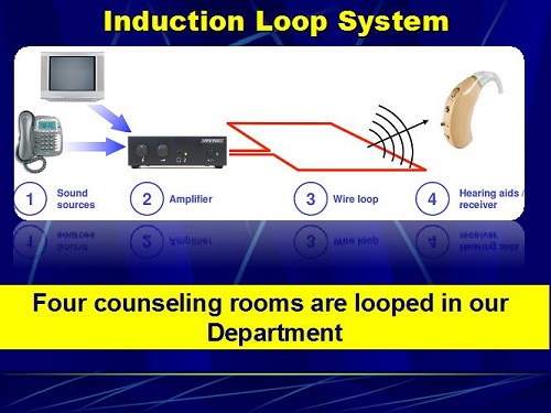
Figure 1. Induction loop system from the sound source to the hearing aid.
We have four counseling rooms in our department. Figure 2 is an example of looping the ceiling and looping the floor. When our audiologist and her husband looped our two counseling rooms, there was no visible wire anywhere in the room. The response on the part of the patients who use it with their telecoil has been tremendous.
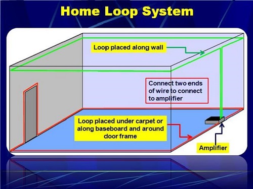
Figure 2: Graphical representation of a floor-to-ceiling loop system.
The telecoil is located internally in the center of the hearing aid. In most hearing aids, it is placed on a diagonal orientation as opposed to horizontal or vertical, which I will address in a few moments. Most telecoils currently have a preamplifier, and they are oriented on a 45-degree or diagonal orientation in most hearing aids. For those of you who are old enough, you might remember a manufacturer who had a hearing aid with two telecoils, one that was vertical and one that was horizontal. I think it was the BT2. There was a switch on this behind-the-ear (BTE) hearing aid where the patient could push it in one direction for vertical orientation and push it the other direction for horizontal orientation. It worked out quite well. The hearing aid was the size of a house, but it worked beautifully with telephone and with loops at that time.
Yanz and Pehringer (2003) provided a summary of recommendations in their article which appeared in a special issue of Seminars in Hearing. According to them, telecoils should be preamplified and programmable. I think it would be fair to say that most are preamplified, and programmability is a nebulous term. Telecoils should also have their own program, independent of other hearing aid programs. Most hearing aids do have that. They also said that it should automatically switch from microphone to telecoil when it detects an electromagnetic signal, which we have now. They also went on to say that when it goes to one ear, it should be in both ears. There are many hearing aids that now have that capability. It should be multi-axis, meaning that it should not be in one fixed 45-degree angle; it should be on several axes so that you can get equal input regardless of what is creating the input source. Lastly, they should develop a simple field strength meter for patients to assess the strength of the signal source. That is what you are asking the telecoil to amplify. I am going to get that later on in the presentation.
I created the following question for some of the test-box manufacturers. “How do I, as a clinician, know that the input signal to the telecoil in the test box is 31.1 or 31.2 mA?” We have the ability to acoustically calibrate the loudspeaker or the probe tubes and microphones in a test box, but we have no way of verifying that the input to the telecoil is what the software says it is. I raised that question, which created an entire journey for a piece of equipment that we are developing here, with the help of Stephen Julstrom from Chicago and an electrical engineer here. I cannot say that it is simple, but it is a first-generation device that I want to share with you at the end of the presentation.
Orientation of the Telecoil
Dave Preves (1996) showed that there are, in essence, two kinds of signals. You have axial, which is straight on, and you have radial, which is up and down or to the sides. When you place the telecoil in the radial electromagnetic field, you get about 6 dB less output than if it was straight on or axial, which is also called the “sweet spot.” Also, when you are using a telephone with the headset directly against the head, for optimal performance, the telecoil should be horizontally mounted. If utilizing a loop, the loop should be vertically mounted for optimal performance. Many manufacturers orient their telecoil diagonally, as a compromise between vertical and horizontal placements. As I said before, ReSound had two telecoils, one that was vertical and one that was horizontal.
Thoughts on the T-coil
These are some random, yet connected, thoughts I have developed over the last two years related to the telecoil. First of all, I think it is fairly accurate to say about 20% to 30% of audiologists verify that the microphone frequency response matches a validated prescriptive target to assure optimal performance. In other words, there are relatively few audiologists who program a hearing aid so that the microphone response is programmed to come as close as possible to a prescribed target. I think it is also equally fair to say that most audiologists do not measure telecoil performance and leave the telecoil to the manufacturer’s default. The telecoil, for some hearing aids, is related to how the microphone is set up. If it is auto-correlated and you change the microphone response, the telecoil response will change in the same manner as the change to the microphone response.
I think it is reasonably fair to say that when audiologists do decide to put a telecoil memory into the hearing aid, most decide to use telecoil only; some decide to use telecoil-plus-microphone. Some manufacturers have a telecoil for telephone communication and another for loop communication. It is rather complex, and the clinicians need to know what is being downloaded into that hearing aid. There is an enormous amount of variability in what kind of default telecoil response you can expect to find when you measure the performance of that hearing aid relative to ANSI 2003. For some manufacturers, the telecoil response perfectly matches the microphone response; for others, it is significantly lower than the microphone response.
I think it is fair to say that audiologists should counsel patients on the use of the telecoil. We have telephones inside all of the booths here at the university. When we get to the telecoil, our audiologists will dial the weather service from that phone, and then train the person how to orient the telephone so they get maximum output or gain from the telecoil. What we are doing is helping them understand that they have to place the telephone receiver not over the ear, but, in the case of a BTE, above the ear. Then they have to move it around so that they get the greatest amount of amplification. I think that is the way most audiologists do this. Later I will share with you a piece of equipment that we developed that is a bit more sophisticated than that.
If your experiences are the same as mine, patients often report that when they switch to the telecoil, the sound is softer and it offers limited benefit. I think this is a relatively common patient report. When that happens, what do audiologists typically do? When I say audiologists, I am talking about me, assuming that I am average. They place the telephone receiver close to the hearing aid and rotate it until they hear the sweet spot, which is when the telecoil finds the axial electromagnetic signal. The patient walks out happy as a frog on a lily pad. Then they come back two weeks later for their hearing aid assessment, and they say they are not hearing well on the telephone. You take the telephone inside the booth and ask them to show you how they are doing this. Nine out of ten patients will take the telephone receiver and place it over their ear canal. You know that you counseled them on this, but you go back and do it all over again. That is my experience, and I am guessing that there are a lot of people out there who share a similar story.
As an explanation for their difficulty, it is often counseled that the difference exists between phones. You may show them that they do great with the phone inside the booth, but when they use the telephone at home, it may not work as well or it may even work better. There are some patients who report that they have several same-model phones in their house, but they do better on one phone than on another, which I call intra-telephone differences, or differences between the same telephone within one person’s home.
Most audiologists do not consider that some, or all, of the problem may be related to a less-than-ideal frequency response for the telecoil, which is called the sound pressure level for an inductive telephone simulator (SPLITS). The ideal frequency response for the telecoil is not known, but matching the programmed microphone frequency response where there is seamless switching between transducers would seem to be a reasonable starting point. There is some concern, however, about interference by providing too much low-frequency gain. To me, it seems that once you have programmed the microphone to match the person’s prescriptive target, you would go in and program the telecoil to match the microphone response. Telecoil measures are made by using a pure tone with a telecoil magnetic field simulator (TMFS) or Telewand or a loop emitting a signal strength of 31.6 mA per meter, which is equivalent to 60 dB SPL. But users do not typically listen to pure tones; they typically listen to speech or music. Later on in the presentation I am going to show you a slide on some measures that we made on the response of a telecoil to a pure tone versus speech.
Back in 2012, Dan Putterman and I published an article in JAAA. We suggest that ANSI might want to consider a different signal in their next derivative of the standard. Instead of using a pure-tone signal, we would like them to use a speech weighted or speech composite signal to measure the performance of a telecoil. In fact, that is now available in the Verifit’s new software, where there are a variety of input signals that one can use when measuring the telecoil response. That is available in the Frye system, but it is not part of the ANSI standard.
Another thought is that average speech at 1 meter is approximately 60 to 65 dB SPL; that is what is used to create the prescriptive target. Speech via telephone, because it is inches from the telecoil, is closer to 80 or 85 dB SPL. A different kind of prescriptive target perhaps needs to be generated for this situation. Lastly, the frequency bandwidth of a telecoil is considerably narrower than the bandwidth of a microphone, and narrower than the bandwidth of the input signal, which is speech or music. These are random thoughts to which I do not have all the answers, but I am beginning to ask the questions and attempt to come up with research projects to get a better handle on these things.
Darryl Teder (2003), in that same special issue of Seminars in Hearing, reminded us that national hearing aid programs in England, Sweden, and Australia specify that the output of the telecoil using a 31.6 mA field, which is the ANSI standard and the microphone frequency response using a 60 dB input, should be within plus or minus 5 dB of each other. In my opinion, this is the same as saying that the relative simulated equivalent telephone sensitivity (RSETS), which we will talk about in a few moments, should be 0 dB plus or minus 5 dB. The clear implication is that 0 dB RSETS is desirable.
The Nordic standard, EN60118-1, came out in 1995 and says that utilizing an inductive signal of 31.6 mA, which is equivalent to 60 dB SPL, shall give the same output as an acoustical input of 57 to 67 dB SPL between 1,000 and 4,000 Hz and 55 to 67 dB between 500 and 1,000 Hz. Again, this suggests that, as a first-order approximation, it might not be bad if the telecoil response matched the microphone response.
For the telecoil to provide maximum benefit for loop and telephone communication, clinicians must pay as much attention to the telecoil frequency response, which is called the SPLITS, as they do the microphone frequency response. We spend a lot of energy getting the microphone response where we want it, and then we forget about the telecoil. The little transducer that is not the big producer is left at the default. That is a fairly accurate assessment of telecoil responses.
Measuring T-coil Performance in a 2cc Coupler
This is going to make the hairs on the back of your neck stand up. We are going to talk about the ANSI S3.22-2003 standard for measuring telecoil performance in a 2cc coupler. It utilizes a pure-tone sweep with a 36.1 mA input using a TMFS or the loop within the test box. One of the things we found when randomly doing this was greater variability in the measured response using the Telewand than when the using the loop. When we do this as a research project, we can use the loop to send the signal instead of the Telewand. That will become clear in a few minutes.
The Telewand is part of the Frye system. Inside the lid of the Verifit system is a T printed on the foam floor, which is where the electromagnetic signal is coming from. This is where you place the hearing aid. With the Frye system, you can either have the manually-held Telewand or you can program the system so that you do not use the Telewand, but rather utilize the loop that is created inside the test box. I will share that with you in a few moments.
The SPLITS is generated using either the Telewand or the loop inside the box. HFA is the high-frequency average utilizing 1,000, 1,600, and 2,500 Hz. RSETS is the difference in the HFA between the telecoil and the microphone averaged across 1,000, 1,600, and 2,500 Hz. Therefore, if RSETS is 0 dB, then the HFA is equal between the transducers at those three frequencies. One of the goals when looking at telecoil performance is that the RSETS to be as close to 0 dB as possible, leaving a seamless impression when the person goes from microphone to telecoil. There will not be a reduction in loudness as it goes from one to the other.
The first step is to place the hearing aid in the test box. The next step is to measure the microphone response according to the ANSI 2003 standard. Then we are going to tell the software to measure the telecoil. Then we are going to stop, put the hearing aid in telecoil, and then measure the telephone frequency response. In this case, we have the telecoil next to the Telewand and the hearing aid coupled to the HA-2 coupler. When you do that, the Frye system generates a graph, shown in Figure 3. The O on the upper curve stands for the output response. The R you see next is the frequency response of the microphone, and the S is the frequency response of the telecoil or the SPLITS.
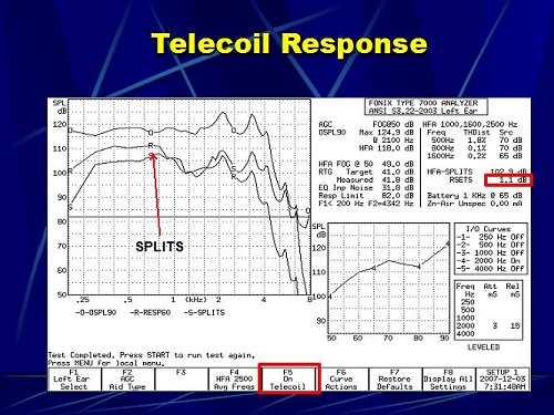
Figure 3. Telecoil response in the Frye test box; O=output response, R=microphone frequency response, S=SPLITS telecoil frequency response.
In the upper right (Figure 3), you see RSETS of 1.1 dB. That means that the overall output at 1,000, 1,600, and 2,500 Hz for the telecoil is 1.1 dB higher than it is for the microphone. You can see that they are very close at 1,000, 1,600, and 2,500 Hz. In order to do that with the Frye system, you have to tell the system in advance that you want to measure the telecoil. As you can see (Figure 3) on the F5 button, the telecoil is on. The default setting is off. If you do not turn that on, then it is just going to go through the traditional measurements and the telecoil will never be measured. That is just a little quirk within the Frye system.
Figure 4 is an example of a hearing aid that I measured not too long ago. Again, the O is the maximum output response. The R is the frequency response of the microphone, and S is the frequency response of the telecoil. The RSETS in this case is -16.4 dB. That means that the overall output of this hearing aid on the telecoil is 16 dB softer on average at 1,000, 1,600, and 2,500 Hz than the microphone. When this patient switches to the microphone from the telecoil, they probably are going to report that it is really soft. We went in and programmed the telecoil to see if we could change that.
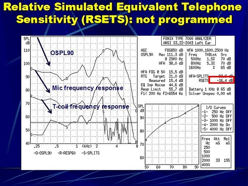
Figure 4. RSETS in a hearing aid where the telecoil was not programmed.
Figure 5 shows the same hearing aid where we went in and corrected the telecoil response. We went from a -16 dB to an RSETS of 5.2 dB, where now the telecoil response is 5 dB louder than the microphone, and that is a 21 dB change by simply going into the software and reprogramming the telecoil so that it comes closer to the microphone response. The patient then has a seamless transition between the microphone and the telecoil.
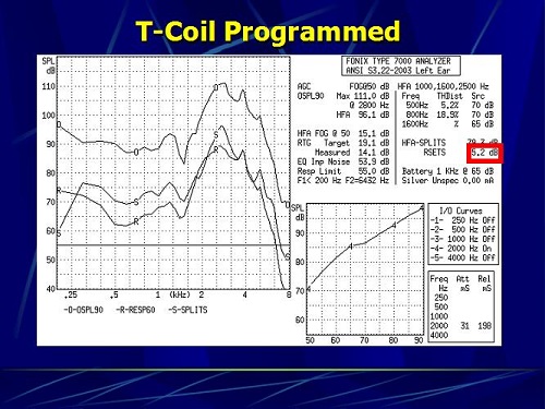
Figure 5. The same hearing aid in which the telecoil was programmed, now giving a RSETS of 5.2 dB.
Going one step further, there is something on the Frye system called coupler multicurve option where you can make multiple measures on one graph and repeat the measures. You can set up the system to do different things; we utilize this for research projects. This is the opening screen on the Frye 8000 (Figure 6). We press F1, which is coupler multicurve. When you do that, the coupler menu comes up (Figure 7). By pressing the menu button on that submenu, the Source Settings menu comes up. By pressing the right button on the front panel of the Fonix 8000, I can tell it that I want the signal to come from the chamber loudspeaker, which is inside the box. I use that when I am testing the microphone. I can press the right button again, and it will change to telecoil. That activates the loop that is built inside the box, and I can measure it now as a loop. The third option is Telewand, where now I am telling the system that I do not want to use the loop inside the box; I want to use this manually-held Telewand. I can tell the system how I want to send the signal from the equipment to the microphone via the chamber or the telecoil via the loop inside the box or via the Telewand. I have a fair amount of flexibility.
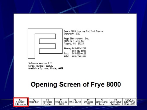
Figure 6. Opening screen of Frye 8000; choosing F1 will open the coupler multicurve screen.
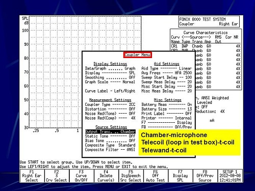
Figure 7. Coupler menu; under Source Settings, the output source can be changed to chamber, telecoil or Telewand.
After I select the output mode, I select F5, where I can tell the system what I want to use as the signal source. My options are DigiSpeech, which is nothing more than a modulated composite speech signal. There is also a composite speech signal, which is exactly the same signal, but it is continuous. If you ran those two signals, they would simply superimpose on top of each other, and as you can imagine, as more input in the low frequencies and less as the frequency increases. I can tell the system that I want to use a pure-tone sweep, and I would select Tone Normal. It would then run a sweep between 200 and 8,000 cycles.
Case #1
We put the hearing aid into the test box. In this case, we programmed the hearing aid microphone to a NAL-NL1 prescription for a hearing loss (Figure 8). That now becomes our reference point for the microphone measure. Prior to doing anything, we took that hearing aid and measured it using real-ear measures. We simply programmed that hearing aid with the software so that the programmed microphone came as close to matching NAL-NL1 as possible, and we set that as program number one. That was our reference point for what follows.
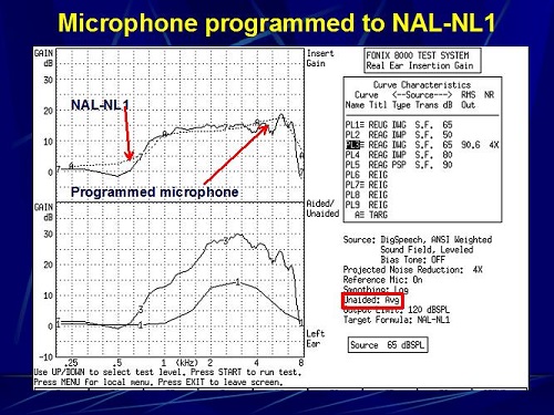
Figure 8. Microphone programmed to meet NAL-NL1 targets (A) as closely as possible.
We took that same hearing aid and we put in three other programs: the manufacturer default telecoil setting for listening on a telephone, the default telecoil setting for listening on a loop, and then a third telecoil setting programmed to match the microphone response. Figure 9 shows a picture of measuring the telecoil inside the test box utilizing the loop. To use the loop, we want the hearing aid to stand up. We oftentimes will place putty at the test point, which is the circle that you see on the mesh floor. I want to show you what we found with all four programs (Figure 10).
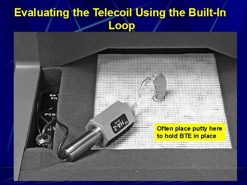
Figure 9. Evaluating the telecoil using the built-in loop in the Fonix 8000.
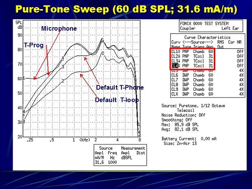
Figure 10. Four pure-tone sweeps for the microphone and three telecoil responses (1=microphone response, 2=default telecoil with loop, 3= default telecoil with phone, 4= telecoil programmed to match microphone response).
Look at Figure 10. The microphone response is on top, which is number 1. Response number 4, which closely matches the microphone, is the programmed telecoil. Number 3 is the default for telephone, and number 2 is the default for the loop. You can see that we came very close to matching the microphone response with that fourth program. What we are doing with that particular project is measuring speech recognition, sound quality and user preference between a telecoil that is programmed to match the microphone and the default telecoil for the telephone and the default telecoil for the loop. So is there any additional benefit in taking the time to program a telecoil to match the microphone, because the microphone has already be matched to the patient’s hearing loss utilizing NAL-NL1? Does it result in speech recognition performance that is significantly better than the default? We do not have any data on that yet. We are currently involved in that project, and those are the questions we hope to answer.
Here is something else that you might find interesting. In Figure 11 we simply ran a pure-tone sweep and a composite speech signal at 60 dB. This is just the input signal that is going to a hearing aid when we utilize a pure-tone signal versus a digital or composite speech signal.
Figure 12, then, is the programmed telecoil and the programmed microphone utilizing a pure tone. Notice that the intensity peak in this particular scenario is around 89 dB, and they are closely matched. I think most people in the audience would agree that, except for below 500 Hz, we did a good job in programming that telecoil to match the response of the microphone.
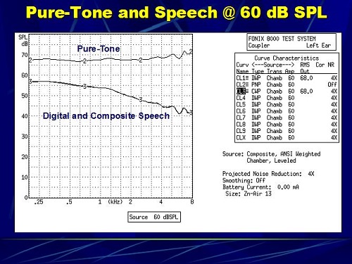
Figure 11. Pure-tone (2) and composite speech (3) runs in the chamber.
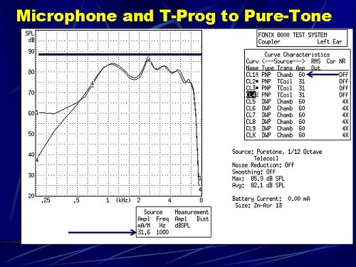
Figure 12. Pure-tone sweep of a hearing aid with a programmed microphone response (1) and telecoil programmed to match the microphone response (2).
In the next scenario, we did not change any of the hearing aid settings; we just changed the text-box signal to digital speech. The input signal was equal at 60 dBSPL and 31.6 mA. Look what happened in Figure 13. First, the responses no longer match. The telecoil response is higher than the microphone’s response. I do not know why. It is just something that we saw. They are still pretty close in terms of the shape. Notice that now the peak energy is down to about 70 dB from 89 dB in the previous scenario (Figure 12). It came down by about 19 dB. I told you in the beginning that I have more questions than answers. Recall also that people who are using hearing aids tell you that it is soft when they switch to the telecoil. We have made the measurement of the hearing aid utilizing a pure-tone signal, but now patients are listening to speech. The output of a hearing aid that was matched before at 89 dB is down now by about 15 to 19 dB when utilizing a speech signal. Perhaps we should be measuring hearing aids with a speech signal as opposed to a pure-tone signal; that may have more real-life relevance than using a pure-tone sweep. Perhaps we should do both: one for the standard and one to see what happens when we use a speech-like signal.
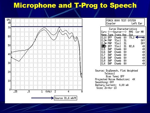
Figure 13. Digital speech run of a hearing aid with a programmed microphone response (1) and telecoil programmed to match the microphone response (4).
The Verifit system allows you to verify the microphone and telecoil responses using different speech signals, represented on a Speechmap. As you can see in Figure 14, it is very close to what we showed you before, where the telecoil response comes very close to the microphone response, in this case, up to 1,000 Hz and above. We were up to 500 Hz and above. This shows you that manufacturers of real-ear and coupler systems seem to be going in this direction.
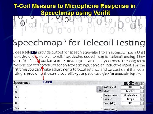
Figure 14. T-coil measurement compared to microphone response on the Speechmap in the Verifit.
Sound Pressure Level of Various Positions of the Telephone at the Ear
This is something that we did when we had nothing to do one day. We put a probe tube in my left ear, and we took the telephone that is inside the booth and used the dial tone. This phone has a maximum and a minimum setting. Using that telephone with the dial tone at a minimum and maximum setting, we wanted to determine the SPL generated by the telephone at the ear as opposed to a meter away. You might find some of this interesting or absolutely boring, but let me walk you through it.
Here is the first measure (Figure 15). This is the SPL at the eardrum with the telephone receiver at the entrance to my left ear and the volume of the telephone set to maximum. You can see that the overall output measured in my eardrum is 96.3 dB SPL. This is tightly coupled to the ear canal of my left ear.
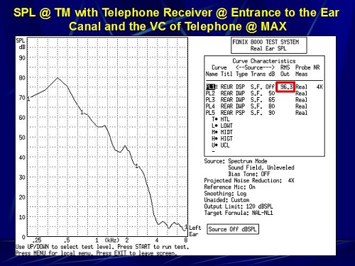
Figure 15. Sound pressure level at the eardrum with the telephone receiver coupled to the entrance of the ear canal and the volume of the telephone set to maximum.
Next, we did the exact the same thing, but with the telephone volume set at minimum. The SPL went down to 81.2 dB (Figure 16). This particular telephone setting reduced the overall input by 15 dB.
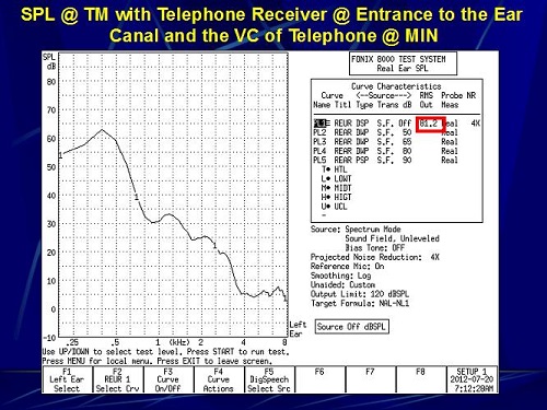
Figure 16. Sound pressure level at the eardrum with the telephone receiver coupled to the entrance of the ear canal and the volume of the telephone set to minimum.
For the next measurement, instead of putting the telephone receiver at the entrance to my ear canal, I put it over the top of my ear where you would normally tell a patient to place it for the telecoil on the hearing aid. How does this change the SPL at the eardrum? In this particular case, it went down to 60.9 dB SPL at maximum (Figure 17) and 53.7 dB SPL at minimum (Figure 18).
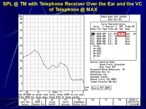
Figure 17. Sound pressure level at the eardrum with the telephone receiver over the ear and the volume of the telephone set to maximum.
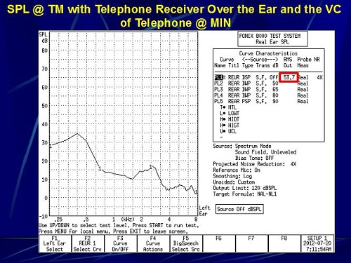
Figure 18. Sound pressure level at the eardrum with the telephone receiver over the ear and the volume of the telephone set to minimum.
The last measure we made was when we took the probe tube out of my ear canal and we placed it on top of my ear. The telephone receiver is now at the probe tube on the top of my ear. Both maximum and minimum measures were taken. Remember that the assumed input from a telephone on the top of the ear is about 80 dB SPL. At maximum volume, this was 71 dB SPL (Figure 19). Then at minimum, it went down to 60 dB SPL (Figure 20). We were trying to find out the SPL on the top of the ear and in the ear canal when using a continuous signal like a dial tone.
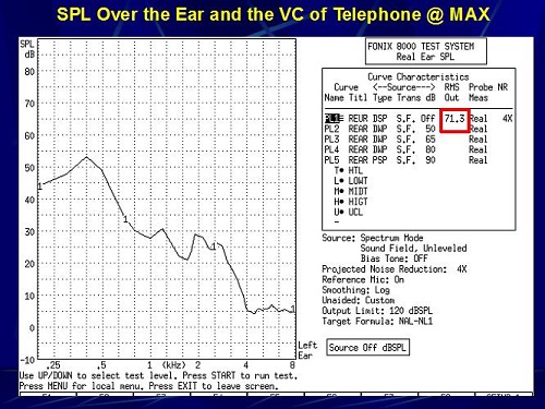
Figure 19. Sound pressure level measured over the ear with the telephone volume set to maximum.
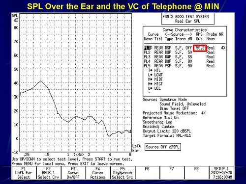
Figure 20. Sound pressure level measured over the ear with the telephone volume set to minimum.
Tools for Assessing T-coil Performance
This is something you might find interesting. We are not happy people here; we are always trying to find ways to improve things. We have been working with electrical engineers here at the university to try and get better at assessing telecoil performance. I must say I am proud of the first one. We were trying to create a device where we could measure a patient’s performance on a telephone. The electrical engineer built this simplistic gizmo (Figure 21). If you look to the lower left where the arrow is, it is just a phono plug. You take that phono plug and you unplug the right or left headphone in your wall panel and insert this. Now we can play recorded words, sentences or sounds from the CD player through the audiometer to the telephone handset that you see to the right in Figure 21. You could take almost any handset and plug it into that box, and whatever signal you were using for speech testing can now be used over a telephone handset.
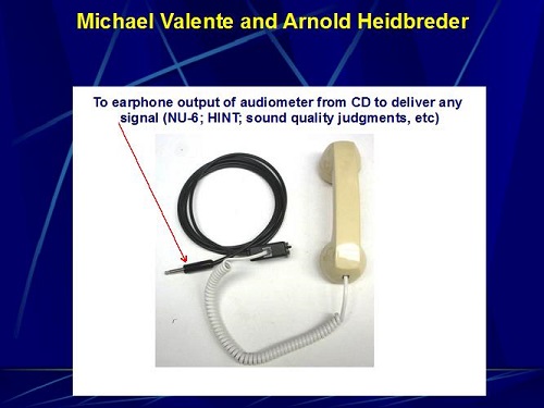
Figure 21. Telephone headset created for use in the audio booth; to be plugged into the headphone or insert earphone jack.
The patient can bring in their own handset. You can get a decent measure of how well they do with their telephone, and you have the opportunity to show them how to manipulate the telephone around their telecoil. You can also make sound quality judgments. You can measure differences in performance by keeping everything the same but changing headsets. It gives us a scientific way of clinically assessing performance with a hearing aid in the T position while using a telephone. This has worked with almost every headset that we tried, except for one that I think was made in the year 1. There might have been mold on it. We put that handset into this device and got absolutely nothing, but the other half dozen worked just fine. We are excited about this as a possible clinical tool to more accurately assess and counsel patients on the utilization of the telecoil with a telephone handset.
This next picture is something that requires a little bit of explanation (Figure 22). This came from hours of work with Stephen Julstrom, who is an electrical engineer from Chicago, Arnold Heidbreder, who is an electrical engineer here at Washington University, Linda Kozma-Spytek from Gallaudet, and me. This started with my frustration of not knowing what the value of the magnetic field that is picked up by a telecoil, as well as my frustration of not knowing what is being generated by the Telewand or the loop in our real-ear and coupler systems. When it says on the software 31.6 mA or 52.1 mA, is that what is being generated inside the test box or by the Telewand? If you are utilizing an FM system or telephone and you have a NoizeFree ear hook over the ear, what is the input signal generated that is picked up by the telecoil? There is no commercially-available device that allows you to know these things.
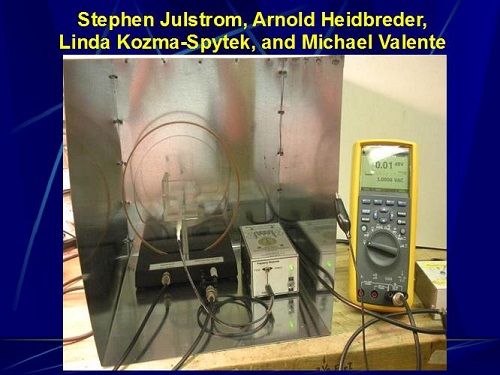
Figure 22. Experimental device to measure magnetic field, developed by Julstrom, Heidbreder, Kozma-Spytek and Valente.
I had some conversations with Arnold Heidbreder. That led to conversations with Stephen and to Linda, with whom I was working on something else. This has been going on for roughly two months. What you see in Figure 22 is the current version of our device to measure these signals. That copper ring you see in the middle is a loop that is generating a signal, and that white thing that you see in the center of it is a probe. By placing a hearing aid in the Plexiglas box that you see in the middle, we can generate a calibrated field at the telecoil of the hearing aid. By utilizing the multimeter on the right, we can know the strength of the electromagnetic field being generated at the point of the telecoil. We are excited about this. I have not used it clinically yet. I don’t know how much this is going to cost me, but this is very close for use here in the clinic. Eventually, we would hope to transform it to something that is commercially available. For the first time, I can begin to make measurements on the input signal going to a telecoil by way of the Telewand, ear hanger or loop within the test box, or the amount generated by a cellphone handset. I am excited about the possibility of getting more objective data as to what are we asking these telecoils to transduce.
The next question I had was, “What if RSETS is not 0 dB?” Say you do ANSI 2003 and it comes up with RSETS of -10 dB. What do you do? I want to show you some software programs that are available that give you a lot of flexibility to shape the telecoil in some cases. I have no commercial interests with any of these manufacturers that I am about to share with you. Figure 23 shows a screen shot of the Widex software with the telecoil program. Here we are fine-tuning the telecoil. As you can see in the Widex software, you can only adjust the overall gain; you cannot adjust different frequency regions.
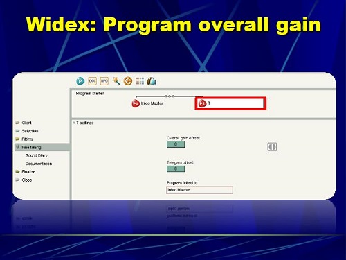
Figure 23. Widex software screen shot to program overall gain in the telecoil.
Figure 24 is Phonak’s software. This is the old Phonak software, but the new version is very similar. It allows you to change the overall gain in the t-coil. There is a little control in the upper right of the Adjust Parameter window that allows you split the screen and change different parameters. If I click that button, I can now make changes in a low, mid, and a high frequency. If I click it again, I can do it in six bands. I click it again, and I can do it in 16 bands. The more bands you have, the greater flexibility you have in programming the telecoil so it matches your programmed microphone response measured in a coupler. The day is coming where you can do it in the real ear, but currently we do it in a coupler.
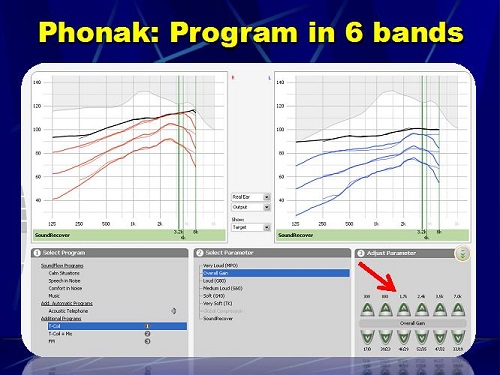
Figure 24. Phonak software screen shot to program overall gain in the telecoil.
Figure 25 is ReSound’s software, where you can measure the telecoil in seven bands. That is the telecoil response.
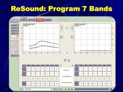
Figure 25. ReSound software screen shot to program overall gain in the telecoil.
T-coil Projects
There are several projects that we are currently working on or thinking of working on here at Washington University. The first one is, “Does programming the telecoil to match the microphone response programmed to NAL-NL1 provide improved sentence recognition compared to the default telecoil setting?” That is one project. A second one is, “Can improved performance in personal use of FM systems be achieved using a NoizeFree ear hanger instead of the neckloop that typically comes with personal FM systems?” This came to me when I was working with a patient and I accidentally put a NoizeFree to the FM receiver as opposed to the loop, and the patient thought that this was amazing. That created some questions and a possible research project. “What is the difference in telecoil response utilizing a speech signal compared to a pure-tone sweep?” We alluded to this earlier. “What is the impact of the low-frequency roll-off on sentence recognition and patient-perceived interference and annoyance?” “Where should the kneepoint be where you begin to see patient annoyance and perceived interference in terms of low frequency roll-off?” “Does programming the telecoil via patient preference provide improved sentence recognition?” We have many areas to examine.
I was using a Contego FM system with a patient a while back. I was using the neckloop of that device, and then I said, “I just wanted to try something.” I took the neckloop off and in its place, I put the ear hanger. I simply coupled that to the FM receiver and placed the ear hangers binaurally. They had ear hangers on both ears, and there was a telecoil on both ears. Her eyes lit up instantaneously like, “What did you do?” That led to another project. “Can you have improved performance with an ear hanger?” Remember that most hearing aid telecoils are at a 45-degree angle, and maybe the ear hanger is better suited to give a better signal than a loop. We are looking at that as a possible project.
Here is something that Kristi Oeding came up with. Kristi is a research audiologist here at Washington University. She wanted to know what would happen if we had a hearing aid prescriptively programmed to the person’s hearing loss and we programmed the telecoil to match the microphone response, and we then gave the telecoil to the patient and let them change the frequency response to their preference, and then measured speech recognition and sound quality. What would happen? Some of you may know that Starkey has this application called SoundPoint, which is available on their software as well as an iPad app, which allows the person to put their finger on a screen and change the frequency gain response of different transducers in real time. Kristi did this on me. We put a hearing aid through a stethoscope and put it on T, and then she played a Rolling Stones song from her phone. As it was playing in my ear, I was rotating my finger up and down, left and right on SoundPoint, and I picked the setting that I thought sounded best to me.
Figure 26 shows you the flexibility in that the Starkey software gives you in terms of programming the telecoil. You can select telecoil in any of the four programs. There are about 16 bands that you can access. When you click on SoundPoint in the Starkey software (Figure 27), it pulls it right up on the screen. You can also do this via an iPad.
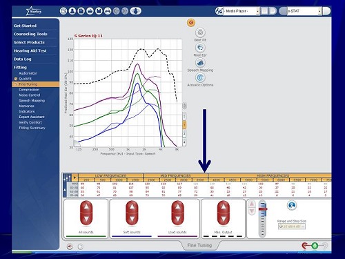
Figure 26. Starkey software screen shot to program overall gain in the telecoil with several frequency bands.
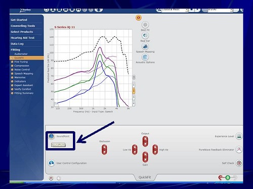
Figure 27. Starkey software screen shot; under QuickFit, you can access SoundPoint.
As you move your finger on the screen, you hear changes that follow the SoundPoint map (Figure 28). When you go to the upper right quadrant, you are decreasing gains in the lows, mids, and highs. When you move down to the bottom, it is increasing the gain in the lows, mids, and highs. It was very easy for me to perceive this, not knowing in advance this is how it worked. The upper left quadrant increases the compression ratio, and, theoretically, that middle quadrant is the best-fit or fine-tuned settings. Of course, the patient does not know how this map is arranged; they are simply rotating their finger. When they find the spot that they like, they click it.
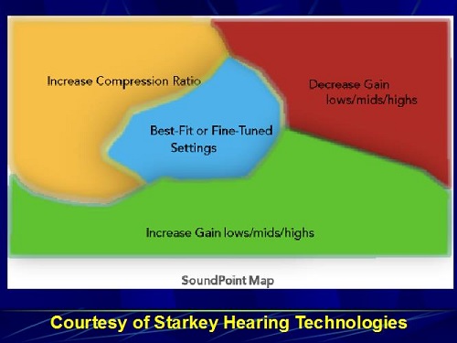
Figure 28. Starkey SoundPoint map, courtesy of Starkey Hearing Technologies.
In this case (Figure 29), the person clicked the A. Then they did a second map, and they clicked the B, which is quite different than A. They went back and forth between the two listening preferences. They select the one that they want by double clicking it. In this case, it was A, and that one becomes the winner. That setting is then downloaded to the patient’s hearing aid.
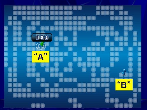
Figure 29. Starkey SoundPoint patient preferences, A and B.
We were interested in finding out what that looks like when measured in the test box relative to the microphone and the programmed telecoil. We also wonder what that does to speech recognition and sound quality in comparison to the telecoil that is programmed. This is an exciting concept that we are trying to investigate.
Questions and Answers
Why are you using handsets when cordless phones are more common in the homes?
That is an excellent question. This is just our first attempt. Our next version will probably go to cordless phones, but we are not quite there yet.
Is there a difference in the frequency response between the neck loop response and the more traditional FM systems?
I do not know the answer to that. I have not made any measures, but you bring up an interesting question, and we can go back and look at that.
Does hearing aid programming software allow linked programming changes to the telecoil response as you program the microphone?
Yes. We have seen that as you change the microphone response, the same change is made to the telecoil response. The problem is that some audiologists are not aware of that, and before they get out of the software, they do not click on auto-correlate. If you do not do the auto-correlate, it will not change the telecoil response. Some software will do this automatically, but many do not. You have to know the software.
References
Preves, D. (1996). Standardizing hearing aid measurement parameters and electroacoustic performance tests (p. 1 - 71). In M. Valente (Ed.), Hearing aids: Standards, options and limitations (pp. 1 - 71). NY: Thieme.
Putterman, D. B., & Valente, M. (2012). Difference between the default telecoil (t-coil) and programmed microphone frequency response in behind-the-ear (BTE) hearing aids. Journal of the American Academy of Audiology, 23(5), 366-378.
Shaw, G. (2012). A surge in hearing loops gives hearing-impaired front row seats. The Hearing Journal, 65(9), 14, 16, 17.
Teder, H. (2003). Quantifying telecoil performance: understanding historical and current ANSI standards. Seminars in Hearing, 24(1), 63-70.
Yanz, J. L., & Pehringer, J. (2003). Quantifying telecoil performance in the ear: common practices and a new protocol. Seminars in Hearing, 24(1), 71-80.
Cite this content as:
Valente, M. (2013, July). The Telecoil: The lonely transducer that can be a big producer. AudiologyOnline, Article #11911. Retrieved from https://www.audiologyonline.com/