
Learning Outcomes
After this course, participants will be able to:
- Describe the difference between near- and far-field hearing situations.
- Describe the different possible characteristics of directional microphone functionality.
- Describe some common factors that can reduce directional performance and how these can be addressed.
Hearing in Noise in the Near vs. Far-field
Hearing in noise is a common challenge for those with hearing loss (Dillon, 2012) and various technologies have been developed to try and improve hearing in these situations. The effectiveness of each is dependent upon a number of factors, including the nature, level and direction of the noise as well as whether the signal of interest originates in the near- or far-field (See Figure 1).
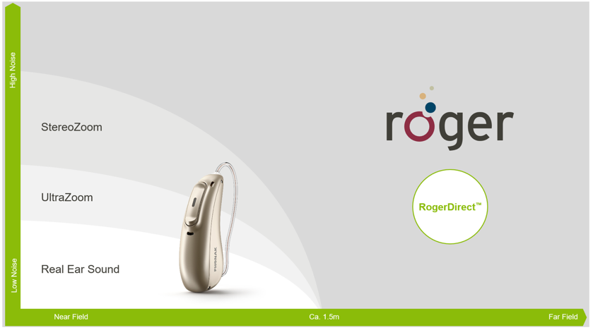
Figure 1. Schematic diagram illustrating the distinction between near-field versus far-field hearing, and effective solutions for each scenario.
The threshold between near vs far-field is dependent upon the acoustics of the listening environment, but is generally around 1.5m from the speaker.
This article is going to focus on the most common solution for improving near-field hearing in noise: Directional microphones, also known as beamformers when there are multiple microphones in the array, and provide a clear explanation of how they work as well as de-mystify some of the jargon used to describe their various behaviors. Beamformers rely on the basic premise that people look at who they want to hear when in noise, providing good sensitivity to the front whilst concurrently attenuating sounds arriving from behind. Their effectiveness is well documented, providing significant signal-to-noise ratio (SNR) benefits over omni-directional microphone modes (e.g., Gravel et al., 1995; Valente et al., 1995). So how do they work?
How Beamformers Work (In a Nut-Shell)
Most hearing aid directional microphone configurations comprise two microphones – a front (M1) and rear (M2) microphone (Figure 2). These are also referred to as monaural beamformers.
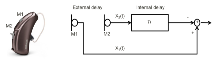
Figure 2. Schematic circuit diagram illustrating how a fixed directional microphone works to provide differential sensitivity for sounds arriving from different locations. Used with permission from Michael Kramer et el.
If we consider a sound originating from behind, it arrives at the rear microphone (M2) before it arrives at the front microphone (M1). This external delay is a function of the physical distance between the microphones, and gives rise to X2(t) and X1(t), respectively (Note: The two microphones need to be a certain minimum distance apart to give beneficial directionality). During signal processing, we can apply an internal delay to X2(t) such that it is out of phase when added to X1(t), providing differential sensitivity for sounds arriving from different locations. Figure 3B shows a cardioid polar plot arising from an internal/external delay ratio of 1.0. There is better sensitivity toward the front (described as the beam) and less sensitivity behind, with the maximal point of attenuation (also known as the null) directly behind at 1800 azimuth.
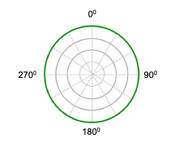
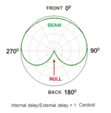
(A) (B)
Figure 3. Polar plots graph the sensitivity of a microphone response for sound arriving from different locations. Generally, the outer most circle indicates 0dB attenuation and each concentric circle moving towards the center reflects increased attenuation. (A) – Omni directional microphone response given by one microphone showing equal sensitivity for sounds arriving from all directions. (B) - Cardioid polar plot, where the area of greatest sensitivity / beam is frontward and the point of least sensitivity / null is at 1800 azimuth. Used with permission from Michael Kramer et el.
On the Level!
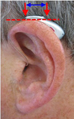
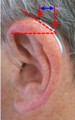
Although the actual physical distance between the two microphones is fixed, the ‘effective’ distance between them is influenced by the way the hearing aid sits behind the ear. When the hearing aid is sitting optimally, the front and back microphones are close to horizontal (see Figure 4A). This means the effective and true physical distance are fairly matched, so the assumed external time delay is accurate, enabling optimal cancellation of sound as per the required polar plot. However, as the hearing aid moves further behind the ear, the so called tilt angle of the microphone increases, reducing the effective distance between the front and back microphones (see Figure 4B).
(A) (B)
Figure 4. (A) – Optimal placement of the hearing aid behind the ear where the front and rear microphones are sitting close to the horizontal plane. Blue arrow shows ‘effective’ distance. (B) – Photo showing the tilt angle caused by a device placement further behind the ear, and the impact this has on the effective distance between the front and rear microphones.
The greater the tilt angle, the smaller the effective distance between the two microphones. The closer the microphones are together in a beamformer, the less directivity (and greater low-frequency roll-off) they provide (Ricketts, 2001). Figure 5 shows the influence of directional microphone tilt angle on directivity. This impact is frequency-specific, having a greater influence on directivity in the higher frequencies, precisely the frequency region where hearing loss tends to predominate (Margolis and Saly, 2008). Fels (2016) presented tilt angle data for both behind-the-ear (BTEs) and receiver-in-the-canal (RIC) hearing aids measured on males, females, children, and KEMAR. These data show a wide spread of tilt angles. For BTEs, tilt angle exceeded 350 in almost a quarter of measurements, which, according to Figure 5, would reduce directivity by ~1dB. For RICs, 70% exceeded a 350 tilt angle, and in 30% of cases, tilt angle was greater than 450, which would be expected to reduce directivity by ~2 dB (Figure 5). Depending on the speech material, SNR, and the starting point on the performance-intensity function, a ~2 dB change can dramatically change speech understanding (MacPherson & Akeroyd, 2014).
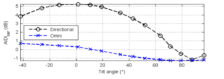
Figure 5. Directivity index for diffuse situations as a function of microphone tilt angle. Used with permission from Stefan Launer.
Interestingly, females were more likely to have larger tilt angles compared with males, possibly due to smaller ear size (Note: the number of children in the data set was very low, making it hard to draw any conclusions here). So receiver/tubing length is not only important for retention and cosmetics, but also for optimal directional performance. I recommend always measuring ear size and checking microphone tilt angle during fitting in order to optimize beamformer performance.
Microphone Matching and Drift
In order for directional microphones utilizing two (or more) individual microphones to work optimally, the microphones need to be matched to each other in both level and phase (Ricketts, 2001). If they are not, the directivity they provide is attenuated, especially in the low frequencies (Ricketts 2001 shows an example where a 1 dB mismatch gives rise to reduction in directivity of 4 dB at 500 Hz!). This drift effect is exacerbated as the distance between the two microphones is reduced, again highlighting the importance of as near-to-horizontal alignment of the microphones as possible. Drift may occur due to debris, moisture, oils etc. differentially affecting either the microphone covers, ports or microphone diaphragms. Prevention is better than cure: Microphone covers are designed to prevent debris impacting on the diaphragm and should be changed when soiled. On top of this, some manufacturers have implemented compensatory systems whereby slightly more//less gain can be added to the output of one microphone prior to their combination for cancellation, in doing so counteracting any issues of mismatch (Ricketts, 2001; Kidmose, 2013). Lastly, some clinically available electroacoustic hearing aid measurement systems (e.g., AudioScan) enable assessment of directional microphone performance in the test box in clinic to guide appropriate action (Wu & Bentler, 2012).
Adaptive Beamformer Behavior
Back to Polar Plots!
We know that in real life, the dominant noise source may not always be directly behind the hearing aid wearer. In some cases, it may be behind and slightly to the side or right/left of the wearer. In such scenarios, a cardioid response will not offer the optimal attenuation of noise and, therefore, most favorable SNR benefits. To overcome this, the internal time delay applied to X2(t) can be varied to create different polar plot patterns that align the null to noise sources arising from different directions (See Figure 6). The ability to adjust this internal time delay and therefore the polar plot pattern is known as adaptive directionality.
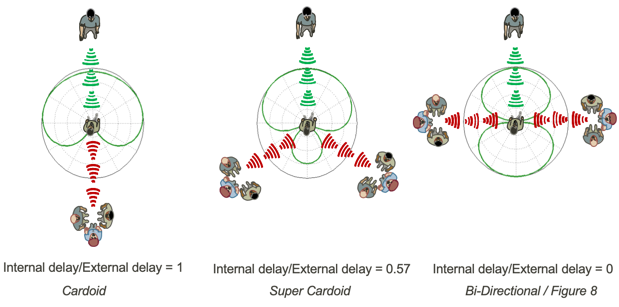
Figure 6. Polar plot patterns created by varying the internal delay imposed on X2(t) relative to the fixed external time delay X1(t), and how these provide optimal performance for different noise source scenarios. Used with permission from Michael Kramer et el.
Furthermore, as signal processing is so fast in modern digital hearing instrument technology, this time delay can be adjusted virtually in real-time, enabling the null to be aligned to a moving noise source in the rear plane. Bentler et al. (2006) compared performance with a two- versus three-microphone beamformer in diffuse noise as well as the influence of fixed versus adaptive behavior across both arrays. Results confirmed that for stationary noise, directional microphones, regardless of microphone number, improved speech intelligibility compared with omni-directional microphones (ODMs). In the moving noise source environment, adaptive behavior resulted in better performance than a fixed, two-microphone beamformer or an omni-directional mode. Blamey et al. (2006) also investigated speech intelligibility in background noise with adaptive directional microphones (ADMs) using both fixed and moving noise sources. Results on the hearing in noise test (HINT, Nilsson et al., 1994) showed both fixed directional microphones (FDM) and ADMs outperformed ODMs, and ADMs outperformed FDMs when noise was located at 1800. For the City of New York (CUNY) sentences (Boothroyd et al., 1985, as cited in Blamey et al., 2006), ADMs delivered significantly better performance than the FDM when noise was either at 1800 azimuth or moving. Subjective data showed ADM was preferred over an ODM response in 54% of listening situations, compared with 17% preference for ODM and 29% ambivalence. So ADMs both outperform and are preferred in situations involving moving noise sources.
Multi-Channel / Multi-Band Beamformers
Input at the microphones can also be considered in frequency-specific channels / bands (Note - these are different than the gain channels that we adjust in the fitting software). Figure 7 shows a schematic diagram for a directional microphone configuration splitting the microphone input into 3 channels: Low frequency (LF), mid-frequency (MF) and high frequency (HF). In such a beamformer, we can create a different polar plot within each channel, enabling alignment of a separate null against the dominant noise in the low, mid and high frequencies.
Applying different polar plots across frequency can deliver several potential benefits. For example, we can align multiple polar plots to more effectively attenuate different noise sources across frequency,. Another example is sound localization for BTE hearing aids. Whilst the longer wavelengths of low frequency sound bend around the pinna, higher frequencies have shorter wavelengths that are diffracted by the pinna, creating a natural directionality and a cue to help front-back sound localization. When we place a hearing aid microphone behind the ear, we lose this cue, impacting on front-back localization. This can be overcome by concurrently applying an omni-directional response in the lower frequencies and a directional response in the higher frequencies. Results show this ‘mixed’ microphone strategy reduces front-back localization confusions by ~21% (Phonak FSN, 2005).
This ‘mixed’ microphone approach has also been found to be effective in balancing wind noise reduction against optimizing speech perception in wind. Hearing aid microphones are designed to detect changes in pressure by sound, however wind turbulence at microphone inlets also creates changes in air pressure which can be converted into an electrical signal and perceived as low frequency noise (Chung, 2012). Chung (2012) investigated the flow noise created at different wind velocities for an ODM, ADM and a mixed microphone response (ODM up to 1000 Hz, and ADM above this). Results showed that the mixed approach allows the user to benefit from the lower wind noise levels from an ODM in the low frequencies whilst concurrently taking advantage of the noise reduction capabilities of direction microphones in the higher frequencies – which are the frequencies where key speech information predominates (Pavlovic, 2018; Pavlovic, 1984).
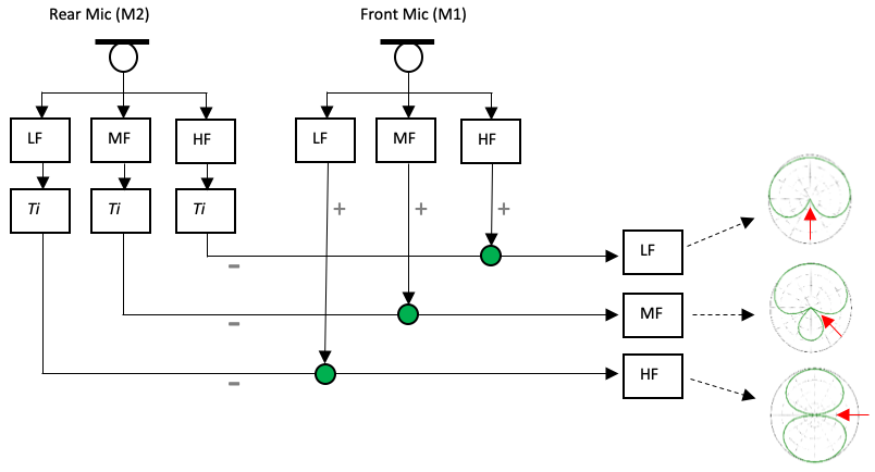
Figure 7. Schematic diagram of a 3 channel adaptive beamformer. The different channels enable a null to be aligned to the dominant noise source in the low, mid, and high frequencies. Ti: Internal time delay. LF, MF, HF: Low frequency, mid-frequency, and high frequency, respectively.
Digital Noise Reduction
Traditional digital noise reduction algorithms use temporal cues to help distinguish between what is speech (typically signals with higher temporal modulation) and noise (typically signals with lower temporal modulation) and reduce gain in channels where the latter dominates. This gain reduction is applied regardless of microphone mode, which is a lost opportunity because when we are in a directional mode the location of the signal of interest is known - it’s right in front! Spatial cues from the beamformer can be harnessed to distinguish between speech from the front and surrounding noise, enabling noise cancellation to be more appropriately applied to further enhance the SNR for speech coming from the front.
True Binaural Beamformers
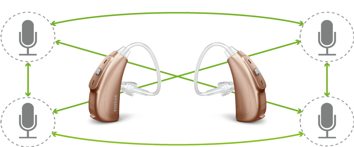
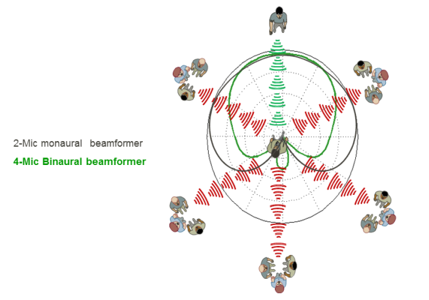
Many clients have concerns with the cosmetics of hearing instruments, and device size can influence hearing aid acceptance and use (McCormack & Fortnum, 2013). This restriction in size coupled with the requirement of a certain physical separation between microphones to achieve beneficial directionality, means most conventional beamformers comprise only two microphones (as outlined in Figure 2). As mentioned, these provide significant benefits in noise in the near field, but may start to have limitations when noise levels reach moderate-to-loud levels. The relationship between greater directivity (and therefore benefit in noise) and number of microphones in a beamformer array is well known (see Dillon, 2001). One way to increase the number of microphones in a beamformer array without adding more microphones to a single hearing instrument is to stream the full audio signal bi-directionally between binaurally fitted hearing aids to create a binaural beamformer. (Figure 8a). In doing so, beam width is substantially narrowed (Figure 8b) and performance in noise significantly improved over what is possible with a monaural beamformer. Initial Phonak field study results showed that StereoZoom (Phonak’s binaural beamformer) provided significantly better performance than a monaural beamformer or omni-directional response for people with severe hearing loss as well as those for more milder degrees of hearing loss even when fitted with open domes (Phonak FSN, 2011). A subsequent study by Picou et al. (2014) compared performance using StereoZoom versus UltraZoom (Phonak’s monaural beamformer) and Real ear sound (Phonak’s BTE pinna restoration algorithm) in listening situations of varying SNR and reverberation levels. They found that in real-world type environments with moderate levels of reverberation, StereoZoom provided significantly better speech recognition than two-microphone beamformers, regardless of the SNR.
More recently, measures of benefit from hearing aids has expanded to include aspects such as listening effort and social interaction. A study by Winneke et al. (2018) investigated listening effort in noise across different beamformer behaviors, collecting both subjective ratings as well as objective measures of alpha band activity via electroencephalography (EEG) to gauge effort. Interestingly, EEG activity in the alpha band was lower and rated ease higher when hearing in noise using a binaural beamformer compared with other less directional microphone approaches. In a separate study by Schulte et al. (2018), participants with hearing loss were invited to communication sessions that were video-taped for later analysis. During these sessions, various microphone modes were implemented (in a blinded way) with the hearing aids they were wearing to see if microphone mode had any impact on communication behavior (e.g., amount of participation, leaning-in behavior - suggesting they weren’t hearing well, etc). Results showed that using a binaural, adaptive beamformer over a fixed monaural beamformer led to significantly increased overall communication (15%) and less leaning-in towards the talker, consistent with the aforementioned SNR and speech perception benefits with this system.
(A) (B)
Figure 8. (A) - Diagram illustrating establishment of a 4-Mic array that can be used to create a binaural beamformer. (B) – Improved directionality provided from a binaural (4-Mic) beamformer (green polar plot) versus a monaural (2-Mic) beamformer (black polar plot) in diffuse background noise. Used with permission from Michael Kramer et el.
These true binaural beamformers shouldn’t be confused with binaural directional systems that may co-ordinate their behavior across ears using communication of meta-data e.g., If criteria satisfied for right hearing aid to go directional -> make the left hearing aid adopt the same / or a different response.
Summary
Hearing aid beamformers are the most effective method for improving SNR and performance in noise for signals arising in the near-field. Binaural beamformers that utilize 4 microphones and work adaptively across multiple channels provide unparalleled performance in these listening situations.
References
Bentler, R., Palmer, C. & Mueller, H. G. (2006). Evaluation of a second-order directional microphone hearing aid: I. Speech perception outcomes. J. Am. Acad. Audiol., Vol. 17(3): pp. 179-189
Blamey, P. J., Fiket, H. J. & Steele, B. R. (2006). Improving speech intelligibility in background noise with an adaptive directional microphone. J. Am. Acad. Audiol., Vol. 17(7): pp. 519-530
Chung, K. (2012). Wind noise in hearing aids: II. Effect of microphone directivity. International Journal of Audiology, Vol. 51, 29-42.
Dillon, H. (2001). Hearing aids. Turramurra, Australia: Boomerang Press
Gravel, J. S., Fausel, N., Liskow, C., Chobot, J. (1999) Children's Speech Recognition in Noise Using Omni-Directional and Dual-Microphone Hearing Aid Technology. Ear & Hearing, Vol. 20(1), 1-11.
Kidsmore, P. (2013) System method for adaptive microphone matching in a hearing aid. US Patent Application (Patent No. US 8,374,366 B2. https://patentimages.storage.googleapis.com/41/52/7b/6b3dedf64f81e2/US8374366.pdf Retrieved on 19/10.2019.
MacPherson, A. & Akeroyd, M. A. (2014) Variations in the Slope of the Psychometric Functions for Speech Intelligibility: A Systematic Survey. Trend in Hearing, Vol. 18, 1-26. https://www.ncbi.nlm.nih.gov/pmc/articles/PMC4227668/pdf/10.1177_2331216514537722.pdf Retrieved on 19/10/2019.
McCormak, A. & Fortnum, H. (2013) Why do people fitted with hearing aids no wear them? International Journal of Audiology, Vol. 52(5), 360-368. https://doi.org/10.3109/14992027.2013.769066 Retrieved on 19/10/2019.
Margolis, R. H. & Saly, G. L. (2008). Distribution of hearing loss characteristics in a clinical population. Ear & Hear., Vol. 29(4): pp. 524-532
Nilsson M, Soli SD, Sullivan JA. (1994) Development of the Hearing In Noise Test for the measurement of speech reception thresholds in quiet and in noise. J Acoust Soc Am, Vol. 95,1085–1099.
Pavlovic, C. V. (2018) SII—Speech intelligibility index standard: ANSI S3.5 1997. The Journal of the Acoustical Society of America, Vol. 143. https://doi.org/10.1121/1.5036206 Retrieved on 19/10/2019.
Pavlovic, C. V. (1984) Use of the the articulation index for assessing residual auditory function in listeners with sensorineural hearing impairment. The Journal of the Acoustical Society of America, Vol. 75, 1253-1258.
Phonak Field Study News (2005) Real Ear Sound - A simulation of the pinna effect optimizes sound localization also with open fittings. Phonak Field Study News, 2005
Phonak Field Study News (2011). StereoZoom – Improved speech understanding even with open fittings. Switzerland: Phonak AG.
Picou, E. M., Aspell., E. & Ricketts, T. A. (2014). Potential benefits and limitations of three types of directional processing in hearing aids. Ear & Hear., Vol. 35(3): pp 339-352
Ricketts, T. A. (2001) Directional hearing aids. Trends in Amplification, Vol. 5(4), 139-176.
Schulte, M., Meis, M., Krüger, M., Latzel, M. & Appleton-Huber, J. (2018) Significant increase in the amount of social interaction when using StereoZoom
https://www.phonakpro.com/content/dam/phonakpro/gc_hq/en/resources/evidence/field_studies/documents/fsn_increased_social_interaction_stereozoom_gb.pdf. Retrieved on 19/10/2019.
Valente, M., Fabry, D. A. & Potts, L. G. (1995) Recognition of Speech in Noise with Hearing Aids Using Dual Microphones. J Am Acad Audio, Vol. 16, 440-449
Fels, L. (2016) Directional microphones: Are we going in the right direction? Exploring the effects of microphone orientation on speech intelligibility in noise. Phonak Audiology Blog: https://audiologyblog.phonakpro.com/directional-microphones-effects-of-microphone-orientation/ Retrieved on 16/10/2019
Winneke, A., Latzel, M. & Appleton-Huber, J. (2018) Less listening- and memory effort in noisy situations with
StereoZoom. Switzerland: Phonak AG. https://www.phonakpro.com/content/dam/phonakpro/gc_hq/en/resources/evidence/field_studies/documents/fsn_stereozoom_eeg_less_listening_effort.pdfRetrieved on 19/10/2019.
Wu, Y-H. & Bentler, R. A. (2012) Clinical Measures of Hearing Aid Directivity: Assumption, Accuracy, and Reliability. Ear & Hearing, Vol. 33(1), 44-56.
Citation
Crowhen, D. (2019). Providing some direction – beamformers explained. AudiologyOnline, Article 26260. Retrieved from https://www.audiologyonline.com

